
Dip soldering method and dip soldering device

A technology of dip soldering and oblique top, which can be used in tin feeding devices, welding equipment, assembling printed circuits with electrical components, etc., and can solve problems such as poor wettability

Inactive Publication Date: 2003-02-12
MATSUSHITA ELECTRIC WORKS LTD +1
View PDF4 Cites 5 Cited by
  • Summary
  • Abstract
  • Description
  • Claims
  • Application Information

AI Technical Summary

Problems solved by technology

However, since lead-free solders generally have poor wettability, dip soldering techniques that can improve the wettability of lead-free solders are currently required

Method used

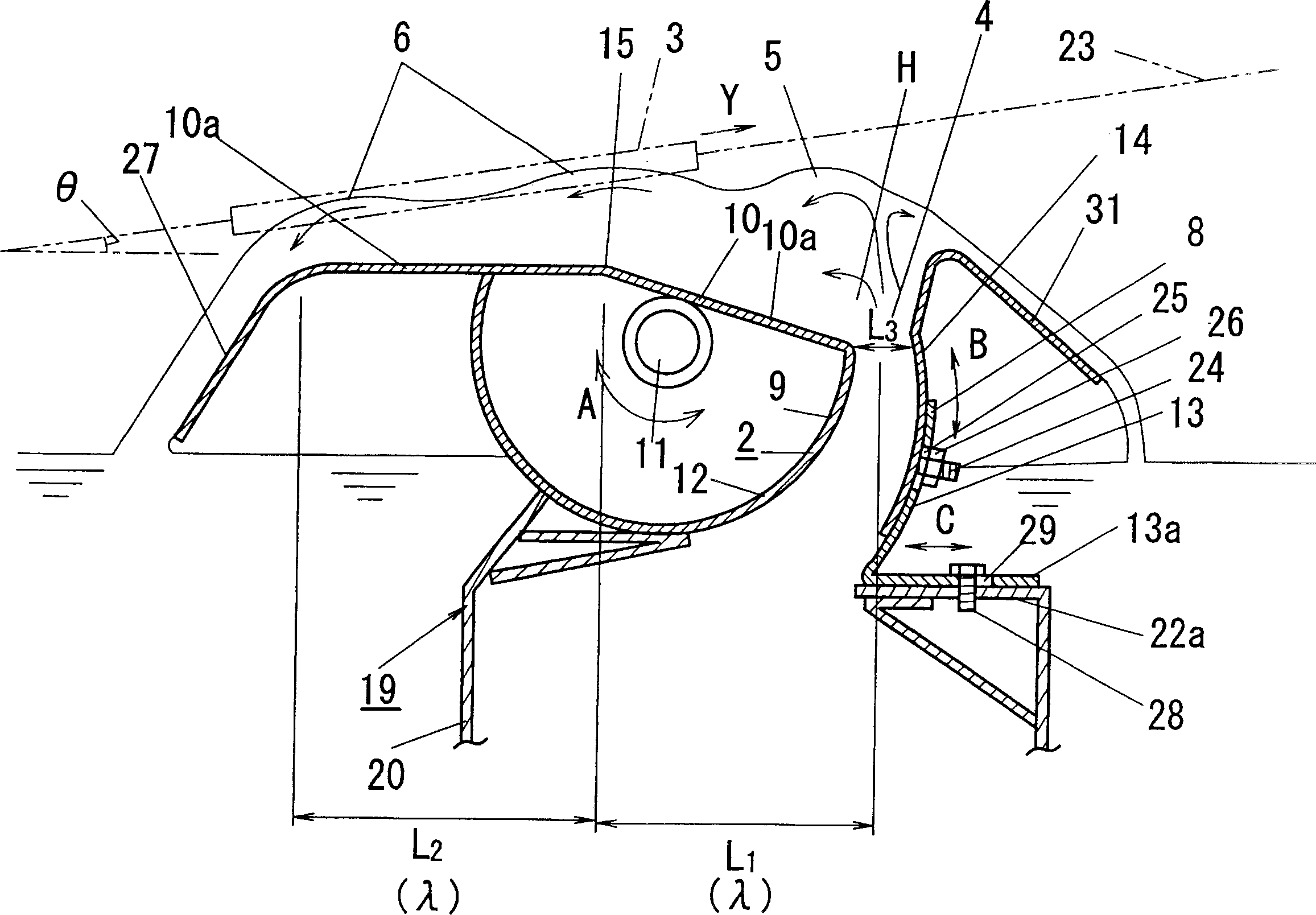

Image

  • Dip soldering method and dip soldering device
  • Dip soldering method and dip soldering device
  • Dip soldering method and dip soldering device

Examples


Embodiment Construction

[0040] The present invention will be described below based on the embodiments shown in the accompanying drawings.

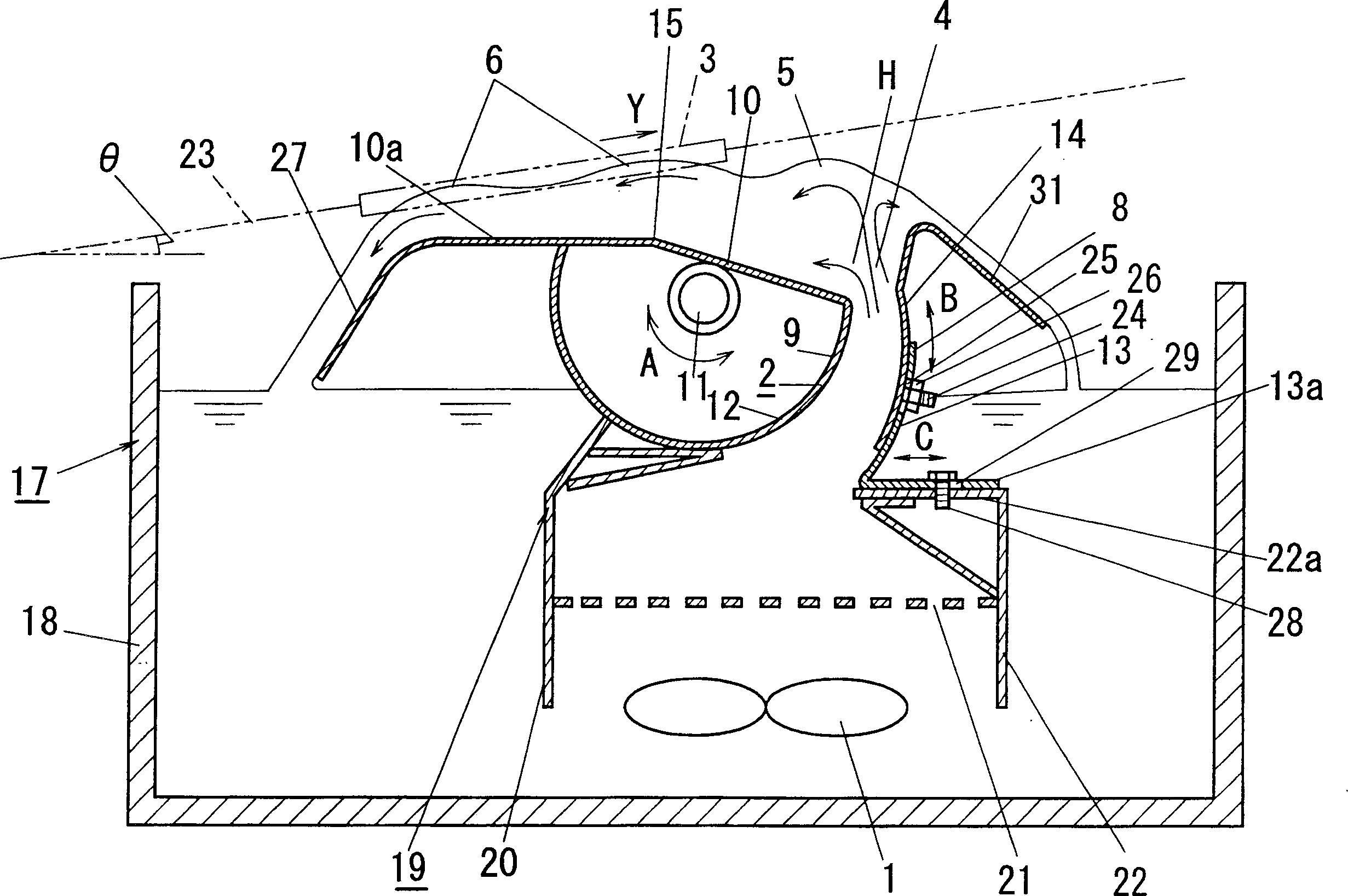
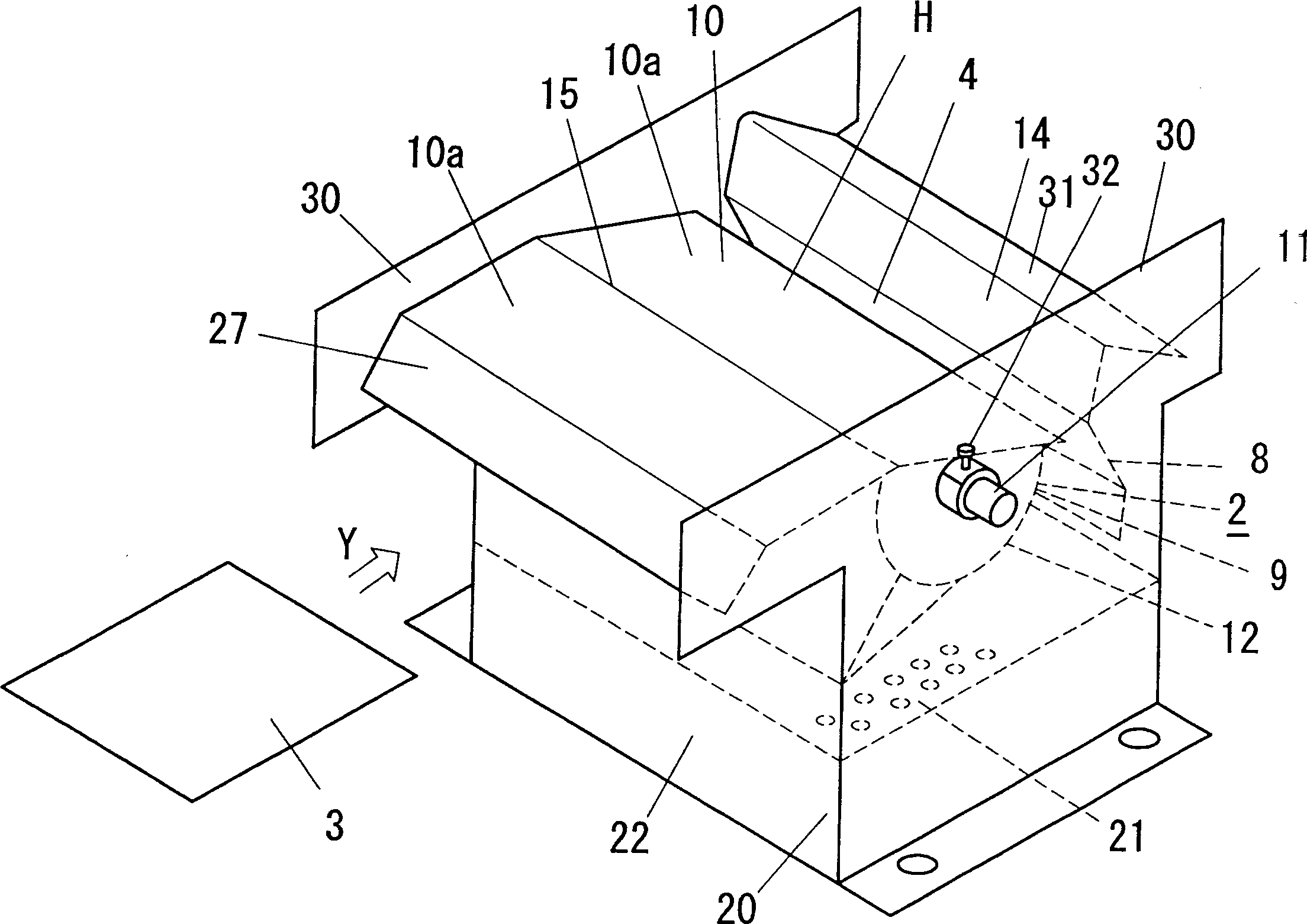
[0041] figure 1 It is a side sectional view showing the solder dipping device of the present invention, figure 2 yes figure 1 Partial perspective view of part of spout 4 shown.

[0042] Such as figure 1 , figure 2 As shown, the dipping soldering device 17 is heated to a solder tank 18 of molten solder in a molten state by accommodating a heater (not shown in the figure) and dips the molten solder contained in the solder tank 18 to the workpiece 3 to be dipped. The molten solder jetting device 19 above is configured, wherein the molten solder jetting device 19 is arranged in the upper part of the solder tank 18 .

[0043] The spout body 20 is set on the molten solder spray device 19, the bottom of the spout body 20 constitutes the lower cylinder portion 22 of the built-in pressure feeding device 1 and rectifying plate 21 such as a pump, and the top of the s...


PUM


Abstract

The present invention relates to a soldering method and soldering device, which can obtain an excellent fillet shape by feeding a sufficient amount of soft solder to a part to be soldered and to secure excellent wettability to realize soldering of high productivity which does not cause defective bridging. In a spout soldering method, a work to be soldered is brought into contact with molten solder spouted from a spout guide upwardly in the reverse-oblique direction to the advancing direction of the plate-like work. The solder is spouted to a horn-like squirt hole from the spout guide and diffused over the horn-like squirt hole in a ridge shape to form a diffused spout part. A ridge-shaped wave spout part is formed by the wave generated when the molten solder flows from the ridge-shaped diffused spout part in a spreading manner. The plate-like work is soldered by bringing into contact with the wave spout part.

Description

technical field [0001] The present invention relates to a soldering method and a soldering device for supplying molten solder sprayed from a jet flow guide to a dipped portion of a workpiece to be soldered such as a printed circuit wiring board on which electronic components are mounted. Background technique [0002] The shape and wettability of the fillet of the part to be dipped are important indicators of the soldering quality at the time of dip-soldering a printed wiring board. That is, supplying a sufficient amount of solder to the part to be soldered of the printed circuit wiring board, and its wettability is good, which is necessary for satisfying good electrical connectivity of the part to be soldered and mechanical connectivity of sufficient strength. very necessary. [0003] It goes without saying that even if a sufficient amount of solder is supplied to the dipped portions to improve the fillet shape, there should be no ensuing bridging of molten solder across th...

Claims


Application Information

Patent Timeline
IPC IPC(8): B23K3/06B23K1/08B23K101/42H05K3/34
Inventor 黑井修一雪桂介宫井隆雄山本修甲斐章则
Owner MATSUSHITA ELECTRIC WORKS LTD
Learn More