Hydraulic energy source equipment

A technology of hydraulic energy and hydraulic source, applied in accumulator devices, fluid pressure actuating devices, measuring devices, etc., can solve problems such as burnout, inability to withstand ultra-high temperature and ultra-low temperature, dry friction, etc., to reduce friction and cost. Low, prolonged working life effect

Inactive Publication Date: 2003-03-05
BEIHANG UNIV
View PDF0 Cites 14 Cited by
  • Summary
  • Abstract
  • Description
  • Claims
  • Application Information

AI Technical Summary

Problems solved by technology

The gap between the friction pairs is very small, and when the oil film cannot be formed, it will cause dry friction

Method used


Image

  • Hydraulic energy source equipment
  • Hydraulic energy source equipment
  • Hydraulic energy source equipment

Examples


Example Embodiment

[0021] The present invention will be further described in detail below in conjunction with the accompanying drawings.
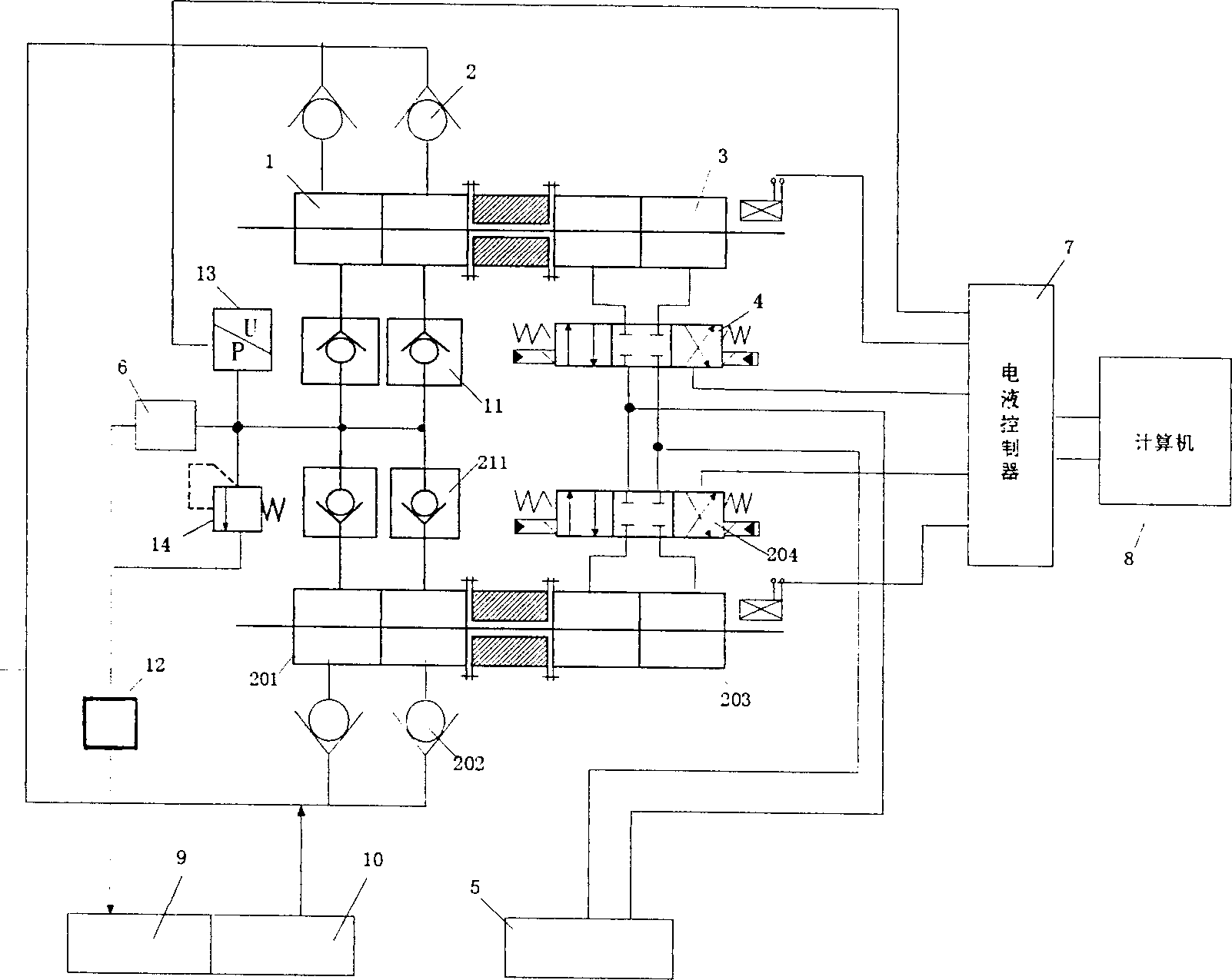
[0022] in figure 2 The high temperature pump set above is composed of a high temperature cylinder 1, two oil inlet check valves 2, two oil outlet check valves 11, and a normal temperature drive cylinder 3. The two oil inlet units connected to the high temperature cylinder 1 The direction valve 2 is connected to the fuel supply tank 10 via a pipeline, and the two oil outlet check valves 11 connected to the high temperature cylinder 1 are connected to the oil return tank 9 via an output pipeline. The test piece 6 is provided on this pipeline. The measuring point of the pressure sensor 13 and the contact point of the overflow valve 14, the sealing ring used in the high temperature cylinder 1 is made of high temperature resistant rubber specially made of fluoroplastic; the normal temperature driving cylinder 3 is connected to the proportional reversing valve through...


PUM


Abstract

The invention discloses a kind of hydraulic equipment working under the ultra-temperature or low-temperature environment. It consists of two sets of high-temperature pump groups paralleled with each other. Each set consists of high-temperature cylinder, one-way oil-input valve, normal-temperature drive cylinder and one-way oil-output valve; the normal-temperature drive cylinder is linked with theproportion-commutating valve through the pine and with the normal-temperature hydraulic source through the other end of the pine; the piston of the high-temperature cylinder moves along with that of the normal-temperature drive cylinder and completes inputting and outputting oils.

Description

technical field [0001] The invention relates to a device for testing the performance of hydraulic components of a pump in a special working environment, more particularly to an ultra-high temperature or low temperature hydraulic energy device, which belongs to the field of fluid control technology. Background technique [0002] Hydraulic components are widely used in machinery, transportation, aerospace and other fields, and their performance can directly affect the quality and performance of the entire equipment. In order to ensure the reliability of its work in some harsh environments, some hydraulic components need to be tested in a special working environment, so it is necessary to provide and test equipment for this special working environment. For example, hydraulic components in the aerospace field are required to work stably with constant hydraulic pressure and hydraulic flow in high temperature (such as up to 160°C) or low temperature (such a...

Claims


Application Information

Patent Timeline
IPC IPC(8): F15B19/00G01M13/00G01M99/00
Inventor 王占林裘丽华祁晓野李运华
Owner BEIHANG UNIV
Why Eureka
Try Eureka