
Sliding component and compressor

A sliding part and compressor technology, applied in the field of compressors, can solve the problems of deterioration of sliding environment and increase of compression load, etc.

Inactive Publication Date: 2003-03-12
TOYOTA IND CORP
View PDF1 Cites 22 Cited by
  • Summary
  • Abstract
  • Description
  • Claims
  • Application Information

AI Technical Summary

Problems solved by technology

However, compared with the use of chlorofluorocarbon refrigerants, the use of carbon dioxide as a refrigerant results in a large increase in the compression load acting on the swash plate through the piston, thereby deteriorating the sliding environment

Method used


Image

  • Sliding component and compressor
  • Sliding component and compressor
  • Sliding component and compressor

Examples


Embodiment Construction

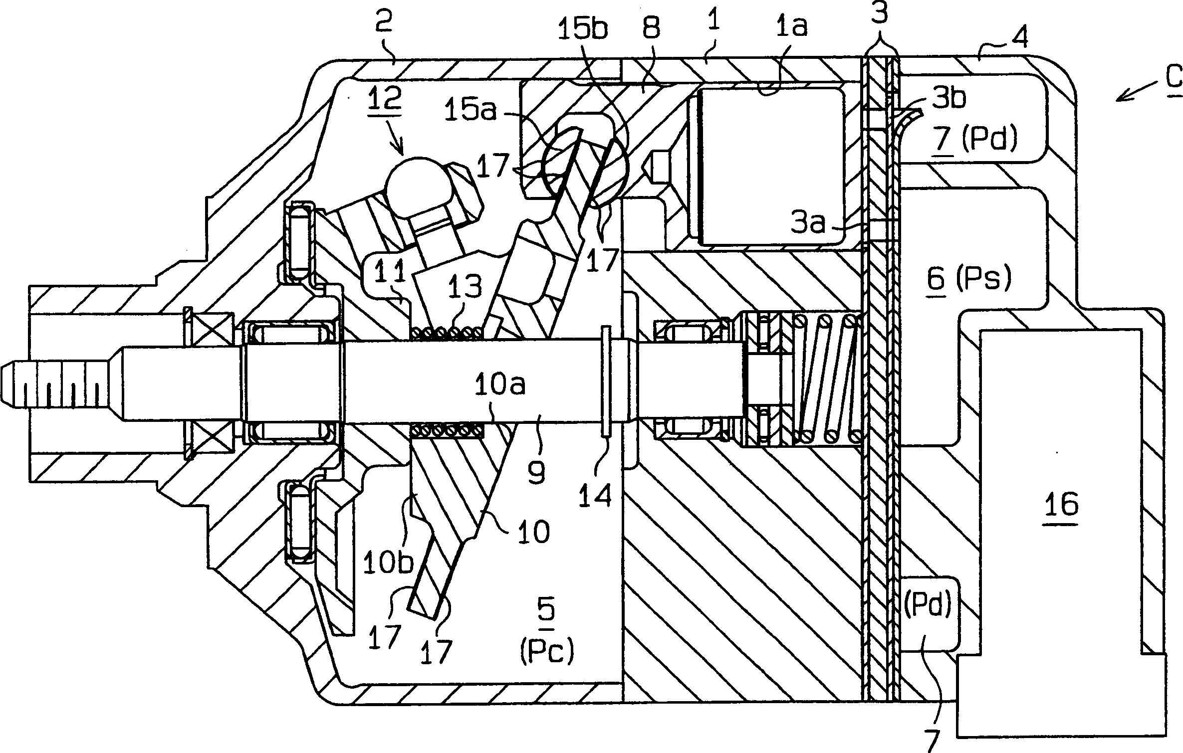
[0015] Below, will refer to figure 1 and 2 The variable displacement swash plate compressor of the present invention will be described.

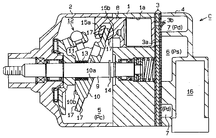
[0016] Such as figure 1 As shown, the compressor C includes a cylinder 1 , a front housing element 2 connected to the front end of the cylinder 1 , and a rear housing element 4 connected to the rear end of the cylinder 1 through a valve plate assembly 3 . The cylinder block 1 , the valve plate assembly 3 and the two casing elements 2 and 4 are connected to each other by some through bolts (not shown), thereby constituting the casing of the compressor C. figure 1 The left side in is the front side of compressor C.

[0017] A crank chamber 5, a suction chamber 6 and a discharge chamber 7 are defined within the compressor housing. A number of cylinder holes 1a (only one is shown) are formed in the cylinder block 1, and a single-headed piston 8 is mounted in each cylinder hole 1a for reciprocating movement. The suction chamber 6 and the dis...


PUM


Abstract

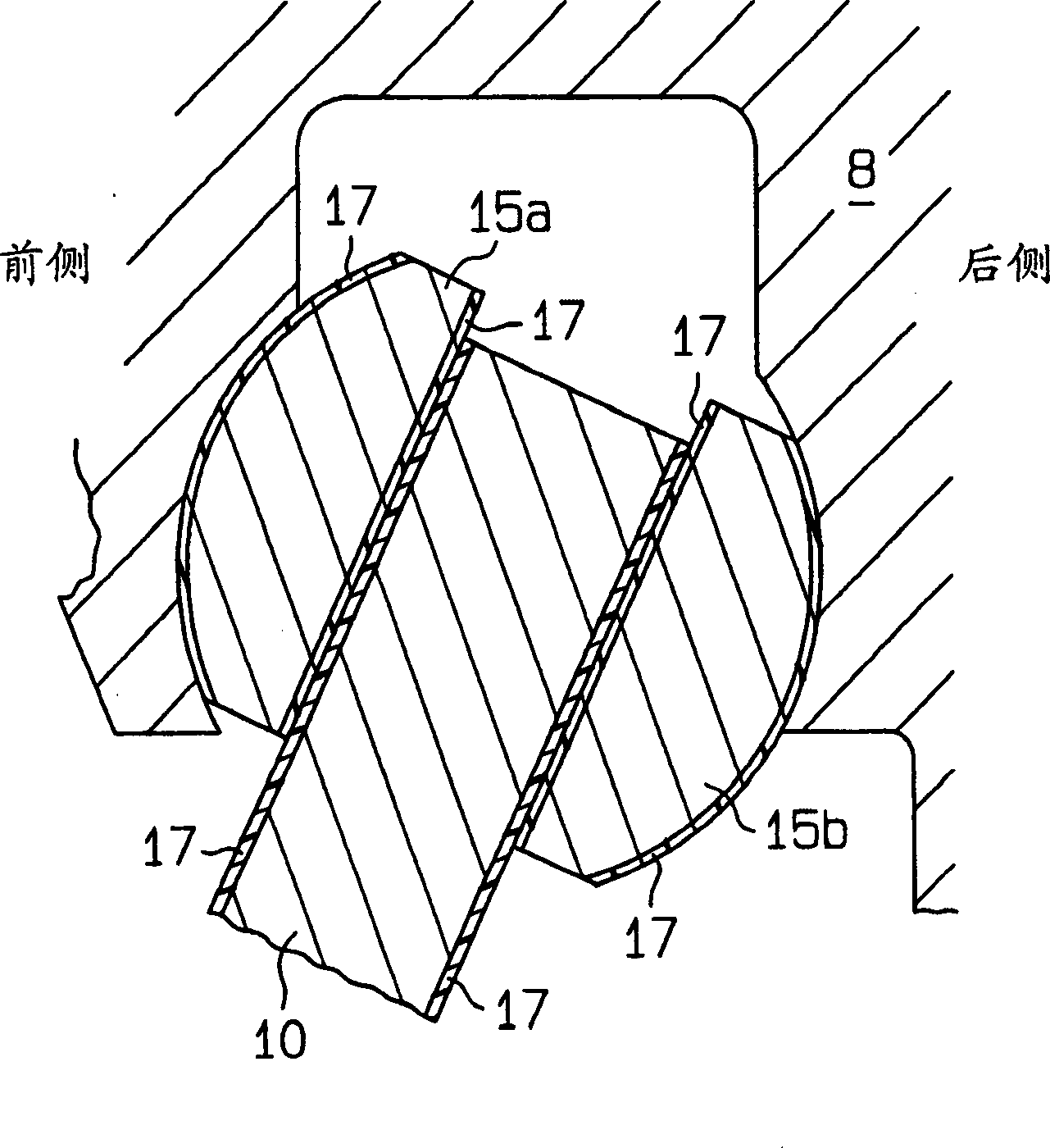
A swash plate (10) is operably connected through a lug plate (11) and a hinge mechanism (12) to a drive shaft (9), and slidably retained on an end part of each piston (8). through a pair of front and rear shoes (15a, 15b). A rotational motion of the swash plate (10) following rotation of the drive shaft (9) is converted through the shoes (15a, 15b) into a reciprocating motion of each piston (8). A thermoplastic polyimide coating (17) is formed on the swash plate (10) and the shoes (15a, 15b) as sliding components of a compressor (C). The thermoplastic polyimide coating (17) may contain a solid lubricant. For the solid lubricant, for example, polytetrafluoroethylene is used. Thus, it is possible to obtain a compressor, which includes the sliding components having improved sliding characteristics, and is manufactured relatively easily.

Description

technical field [0001] The invention relates to a sliding part for use in, for example, a compressor of an air-conditioning system, and also to a compressor. Background technique [0002] Lubrication of the sliding parts constituting the internal mechanism of the compressor is generally performed by making lubricating oil contained in the compressor form oil mist together with refrigerant gas (refrigerant gas such as chlorofluorocarbon gas, etc.) circulating in the operating compressor and Carry out lubricating oil in the form of oil mist to each sliding part. However, when the compressor is restarted after a long period of non-operation, the lubricating oil adhering to the sliding parts is washed away by the refrigerant gas. [0003] For example, in a swash plate compressor, each piston is connected to the swash plate through sliding shoes, and reciprocates in the cylinder bore through the rotation or sliding of the swash plate. The swash plate and shoes begin to slide im...

Claims


Application Information

Patent Timeline
Patent Type & Authority Applications(China)
IPC IPC(8): F04B39/00F04B27/08F04B27/10F16C33/20
CPCF05C2253/12F04B27/1054F04B27/0886
Inventor 下俊久村濑仁俊
Owner TOYOTA IND CORP
Learn More