Chemical sensor made of nano particle/dendrite composite material

A chemical sensor and nanoparticle technology, applied in the field of chemical sensors, can solve problems such as difficult identification, and achieve the effect of improving sensitivity and response time

Inactive Publication Date: 2003-03-12
SONY INT (EURO) GMBH +1
View PDF8 Cites 17 Cited by
  • Summary
  • Abstract
  • Description
  • Claims
  • Application Information

AI Technical Summary

Problems solved by technology

When using only 5ppm of toluene vapor, the signal is u

Method used


Image

  • Chemical sensor made of nano particle/dendrite composite material
  • Chemical sensor made of nano particle/dendrite composite material
  • Chemical sensor made of nano particle/dendrite composite material

Examples


Embodiment Construction

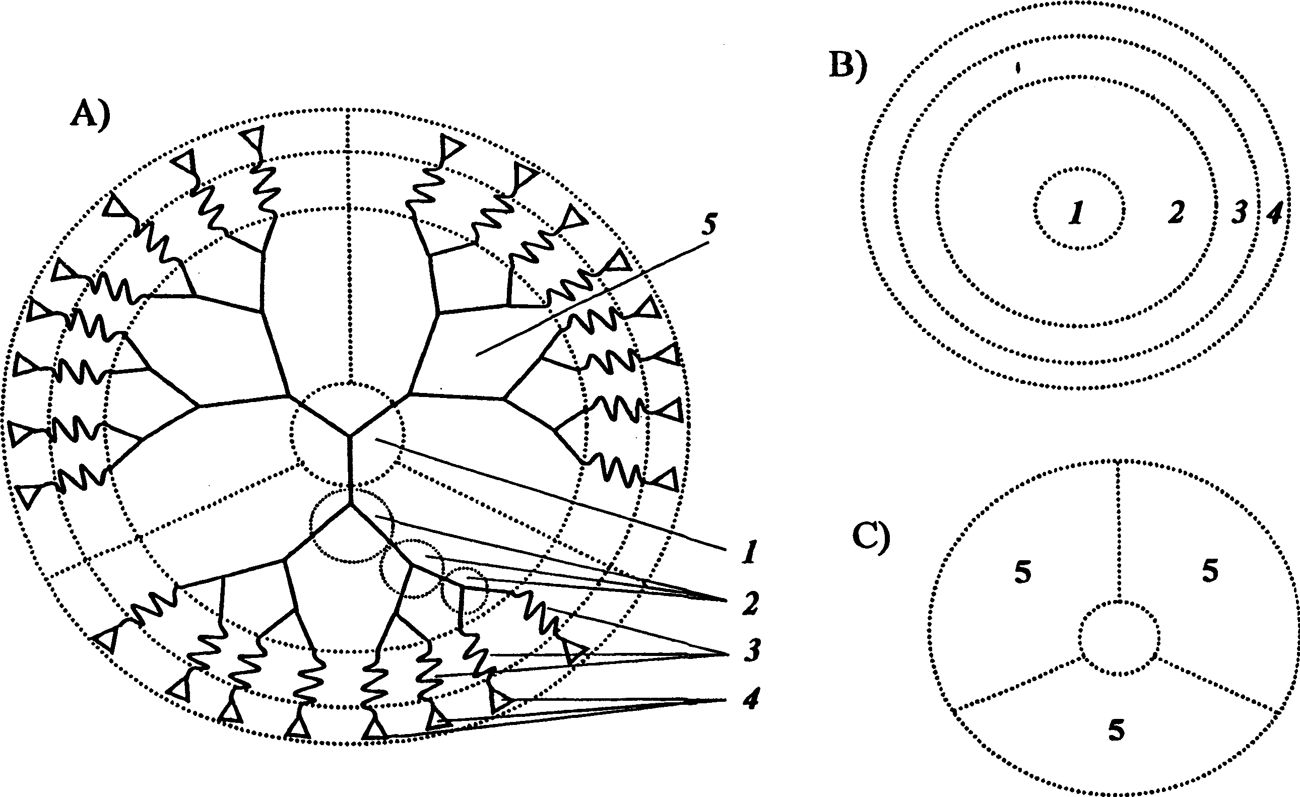
[0109] figure 1 A shows the general structure of dendrites that can be used to shape the chemical sensors of the present invention. The center of the structure is center 1 (or focus). figure 1 In the case of A, there are three branches in the center (such as 1, 3, 5 substituted benzene rings). However, the center can generally also have a different number of branches. Preferably the center has two arms (eg 1,4 substituted benzene ring or alkylenediamine). More preferably the center has three wings (eg 1,3,5 substituted benzene ring). Even more preferably the center has four wings (eg carbon or silicon atoms). Each wing in the center is connected to the first "shell" of repeating unit 2, each splitting into two new wings. The atoms of the repeating unit branches may be carbon atoms or heteroatoms such as nitrogen. figure 1 The example shown in A has a total of three repeating unit shells from the center to the outside of the structure. The dendrite structure shown is the...


PUM


Abstract

The invention relates to a chemical sensor comprising a sensor film formed of a nanoparticle network in which the nanoparticles are interlinked by functionalized dendrimer molecules. The dendrimers support an efficient uptake of analyte molecules by the film material and therefore enable a high sensitivity of the sensor. In addition, the chemical nature of the dendrimers strongly determines the chemical selectivity of the sensor device. By cross-linking the components of the sensitive material the sensor displays a good mechanical stability.

Description

technical field [0001] The present invention relates to a chemical sensor, a method of obtaining the chemical sensor and a method of detecting an analyte using said chemical sensor. Background technique [0002] Much effort has been made in recent years to develop devices that mimic the senses of smell and taste. These devices, commonly referred to as electronic noses and electronic tongues respectively, are applicable to a wide range of applications, such as entertainment robots, identification systems, quality control systems, environmental monitoring, and medical diagnosis. However, only a limited number of electronic nose devices are currently commercially available. Although these devices can identify and differentiate some "smell" samples, further improvements are still needed to meet the requirements of many advanced applications mentioned above. These applications usually require higher sensitivity, higher discrimination, faster response, better stability and lower...

Claims


Application Information

Patent Timeline
IPC IPC(8): G01N21/64C09K3/00G01N5/02G01N21/27G01N21/77G01N27/12G01N27/22G01N33/00G01N33/543
CPCY10T436/11G01N27/126G01N33/0001G01N21/77B82Y15/00B82Y35/00
Inventor T·沃斯梅耶安田章夫R·E·保尔K·米伦
Owner SONY INT (EURO) GMBH
Why Eureka
Try Eureka