DC system short circuit protection device

A DC system and short-circuit protection technology, applied in emergency protection circuit devices, electrical components, etc., can solve the problems of difficulty in setting DC current and time, long time to remove faults, and inability to realize automatic adjustment of operation mode, to overcome the disappearance of DC power. , the effect of protecting reliability and improving reliability

Inactive Publication Date: 2003-03-12
STATE GRID GANSU ELECTRIC POWER CORP +1
View PDF0 Cites 20 Cited by
  • Summary
  • Abstract
  • Description
  • Claims
  • Application Information

AI Technical Summary

Problems solved by technology

Its main disadvantage is: the thermal brittleness of the fuse
When used in AC, it has the advantages of good selectivity and simple operation and maintenance;

Method used


Image

  • DC system short circuit protection device
  • DC system short circuit protection device
  • DC system short circuit protection device

Examples


Embodiment Construction

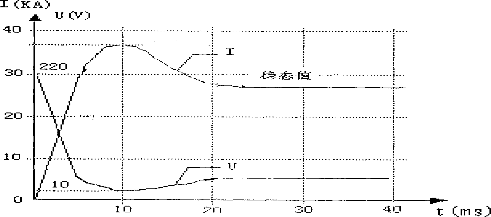
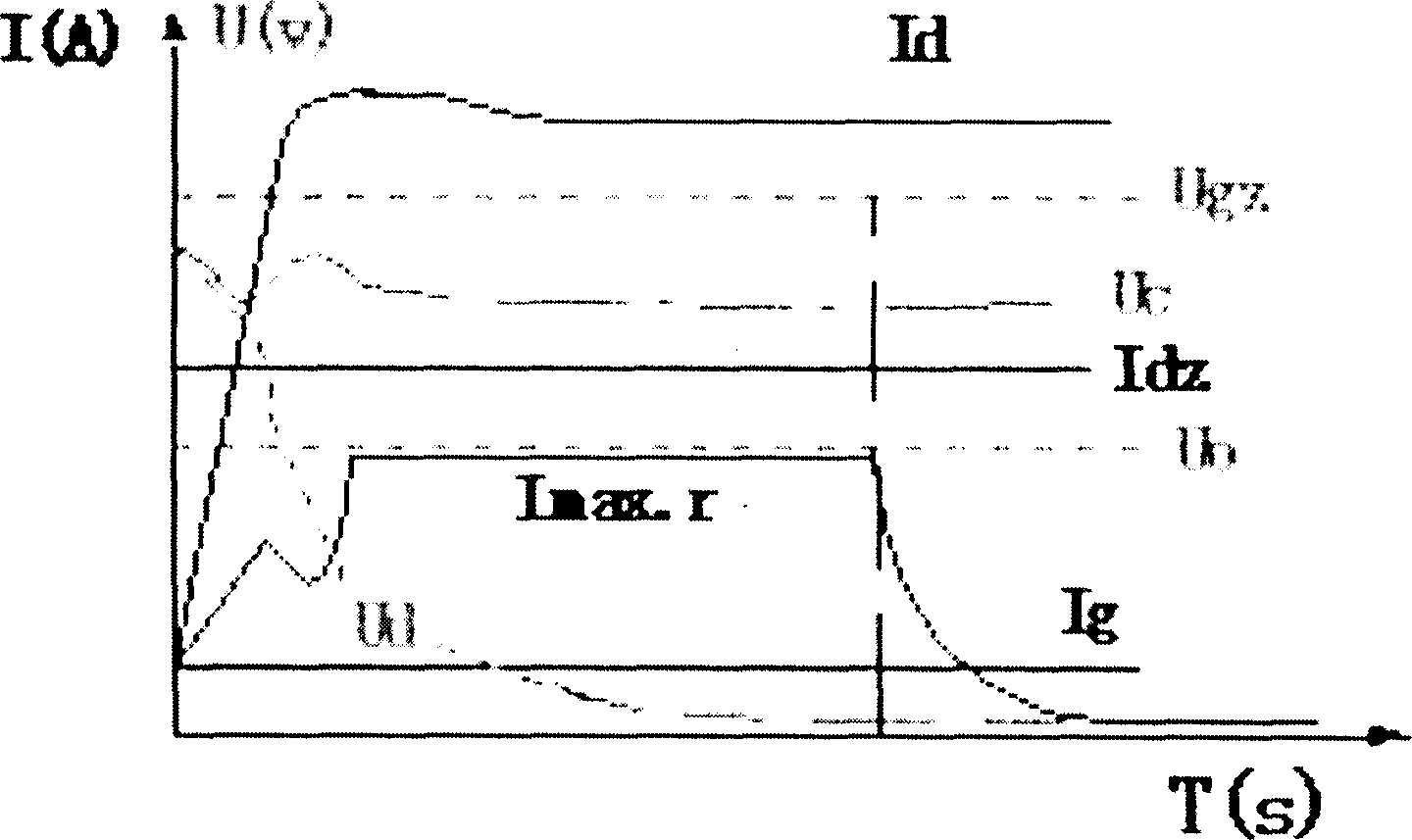
[0017] Before describing the embodiment of the present invention, the current and voltage criteria are explained in detail: the current and voltage criteria are provided by the following background technology. The biggest feature of the DC system is that the power supply line is short, the short-circuit current of each branch and the short-circuit at the head end of the power supply The current difference is small, the short-circuit current is large, the short-circuit point and the bus voltage are very low, and the dynamic process is shown in figure 1 shown. The ordinate in the figure is the current and voltage coordinates, and the abscissa is the time coordinate. The short-circuit current curve I rises rapidly at the initial stage of short-circuit, and then enters a stable state. The short-circuit voltage curve U decreases rapidly at the initial stage of short-circuit, and then enters a stable state. According to the capacity and internal resistance of the current domestic...


PUM


Abstract

The protection device is suitable to the on-line protection of the short circuit failure at DC 220 voltage, +/- 110 voltage in power plants and transformer substations. The invention is realized through following steps. The detection circuit for the short circuit in the branch through the data collection circuit, A/D conversion circuit is connected to the industrial control computer. The detection circuit for the bus voltage through the data collection circuit, A/D conversion circuit is connected to the industrial control computer. The detection circuit for the state of the breaker through the optical isolation input circuit is connected to the industrial control computer. The current criterion is I is greater than or equal to Id, and the voltage criterion is U is less than or equal to Ud.

Description

technical field [0001] The invention relates to a short-circuit protection device, which belongs to a short-circuit protection device of a DC system suitable for on-line protection of short-circuit faults in power plants and substations with DC 220 volts and ±110 volts. Background technique [0002] The DC system is the power source for control, protection, signal and automatic devices in the power system, and its reliability is directly related to the safety of the power system. However, at present, the traditional fuse method is still used for fault removal after a short circuit in the DC system, and due to a series of legacy problems such as the dispersion and thermal brittleness of the fuse, the leapfrog action of the fuse to the total fuse of the DC power supply has repeatedly occurred. Cause the DC power supply to disappear, lead to the rapid spread and expansion of power system accidents, and cause catastrophic equipment damage and system accidents in the power system...

Claims


Application Information

Patent Timeline
IPC IPC(8): H02H7/26
Inventor 张忠元赵登福董继民冯书安李世伟彭夕岚
Owner STATE GRID GANSU ELECTRIC POWER CORP
Why Eureka
Try Eureka