Control method for hydraulic pinch roll and controll apparatus thereof

A control device and control method technology, applied in rolling mill control devices, metal rolling, manufacturing tools, etc., can solve problems such as repeated unevenness of the end surface of the coil, poor coil shape, and poor coil coil shape

Inactive Publication Date: 2003-03-19
IHI CORP
View PDF0 Cites 11 Cited by
  • Summary
  • Abstract
  • Description
  • Claims
  • Application Information

AI Technical Summary

Problems solved by technology

[0006] In the past down coiler 2, when the planar shape of the coiled steel strip 4 is not good, and when the strip steel 4 enters the pinch roller 1 eccentrically, such as image 3 As shown, the winding shape of the

Method used


Image

  • Control method for hydraulic pinch roll and controll apparatus thereof
  • Control method for hydraulic pinch roll and controll apparatus thereof
  • Control method for hydraulic pinch roll and controll apparatus thereof

Examples


Embodiment Construction

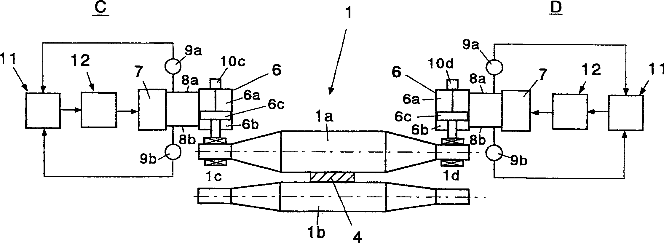
[0021] Figure 5 The overall configuration diagram showing the first embodiment of the pinch roller according to the present invention is shown, and the parts common to those in FIG. 2 are denoted by the same reference numerals, and overlapping descriptions are omitted.

[0022] In the apparatus of the present invention, the pressing force of the upper pinch roll 1a with respect to the steel strip 4 is controlled by the pressing force control devices C and D on the left and right, as in the conventional apparatus of FIG. 2 . That is, according to the pressure P of the cylinder head end 6a and the piston rod end 6b of the hydraulic cylinder 6 detected by the pressure detectors 9a and 9b provided in the middle of the pipes 8a and 8b a , P b , the pressing force F generated by the hydraulic cylinder 6 is calculated by the calculator 11, F=P a ×A h -P b ×A 1 (where, A h , A 1 Represents the area of ​​the cylinder head end and the piston rod end of the piston 6c), which is c...


PUM


Abstract

The present invention is the control method and controller for hydraulic pinch roll. The controller is provided with position detector for detecting the positions of the pistons in the right and left cylinders, calculator for calculating the difference between the outputs, control unit for processing and giving correction output and addition and subtraction calculator for operation based on the set extrusion force. The control method includes applying correcting output from the controller to one side of the pinch roll for increasing the extruding interval and applying corresponding correcting output from the controller to the opposite side of the pinch roll for decreasing the extruding interval so as to control the extrusion and improve the winding shape.

Description

technical field [0001] The present invention relates to a method and apparatus for improving the coil shape of a coil wound on an downcoiler by hydraulic pinch rollers controlled by hydraulic cylinders and servo valves. Background technique [0002] FIG. 1 shows the pinch rolls 1 of the downcoiler 2 of the hot rolling plant, the object of the present invention. In the hot rolling facility, the strip 4 rolled by the finishing mill 3 to the desired thickness is coiled by the downcoiler 2 to obtain a final product in the form of a coil. The function of the pinch rolls 1 is to guide the strip 4 moving on the table drum 5 to the downcoiler 2 . [0003] As shown in FIG. 2, recently, hydraulic pinch rolls in which the positions of the upper and lower pinch rolls and the pressing force on the strip 4 are controlled by the hydraulic cylinder 6 and the servo valve 7 have been put into practical use. The function required for such a pinch roll is to pull the strip 4 to the downcoiler...

Claims


Application Information

Patent Timeline
IPC IPC(8): B21B39/00B21B15/00B21B37/68B21B41/12B21C47/00B21C47/34
CPCB21B39/006B21B2015/0057B21C47/003B21C47/3425B21C47/34B21B37/68B21B41/12
Inventor 桑野博明白川孝司
Owner IHI CORP
Why Eureka
Try Eureka