
Dynamically positioned semi-submersible drilling vessel with slender horizontal braces

A technology of horizontal tie rods and tie rods, which is applied in the direction of ship hulls, motor vehicles, ship construction, etc., and can solve the problems of affecting the weight of the ship, unfavorable, and increasing the area of ​​the ship's water plane

Inactive Publication Date: 2003-03-19
高曼海洋工程联合有限公司
View PDF3 Cites 28 Cited by
  • Summary
  • Abstract
  • Description
  • Claims
  • Application Information

AI Technical Summary

Problems solved by technology

A disadvantage of diagonal tie rods is the increase in the waterplane area of ​​the boat, which adversely affects the weight of the boat, wave resistance and overall cost

Method used


Image

  • Dynamically positioned semi-submersible drilling vessel with slender horizontal braces
  • Dynamically positioned semi-submersible drilling vessel with slender horizontal braces
  • Dynamically positioned semi-submersible drilling vessel with slender horizontal braces

Examples


Embodiment Construction

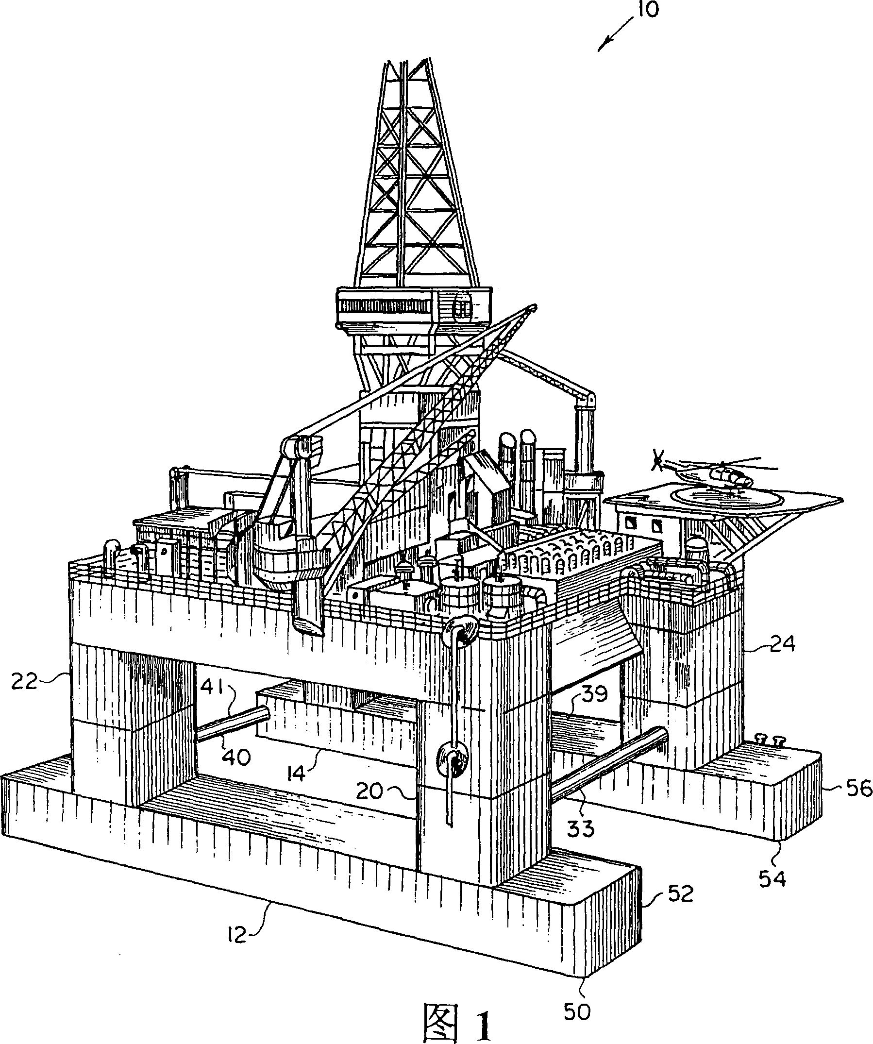
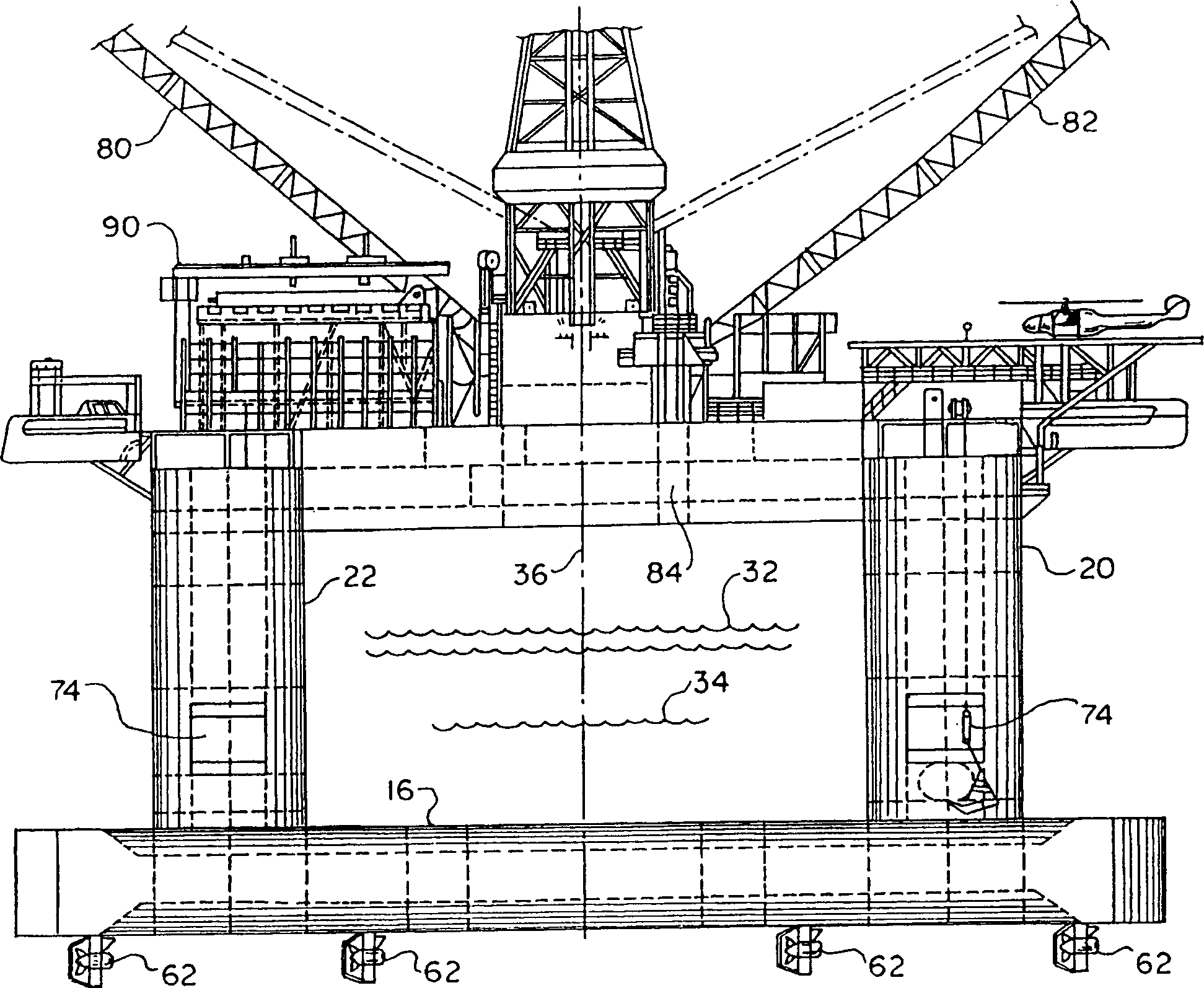
[0030] Referring now to the accompanying drawings in detail, numeral 10 denotes a semi-submersible vessel of the present invention. As will be described in more detail below, the vessel includes a pair of buoyant or submerged tanks 12, 14, wherein the submerged tanks are divided into a plurality of watertight compartments for containing ballast and allowing access to the thruster assemblies . Secured to the upper portions 16 and 18 of the diving tanks 12 , 14 respectively are columns or caissons 20 , 22 , 24 and 26 extending in a direction transverse to the vertical axis of the diving tanks 12 , 14 .

[0031] The upper part of the columns 20, 22, 24 and 26 is supported by a platform 30 for supporting mineral exploration and production operations. Such as figure 2 As shown, portions of columns 20-26 and submersible tanks 12 and 14 are submerged to an operating draft 32, while upper portions of columns 20-26 and platform 30 are raised above the maximum expected water wave heig...


PUM


Abstract

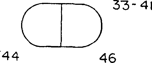
The invention relates to a semi-submersible vessel designed to operate in harsh environment. The vessel has a twin-hull pontoon structure that supports four corner caissons extending vertically from the pontoons above an operational draft of the vessel. A pair of slender parallel horizontal braces connects each pair of opposing caissons, the braces extending in a general plane perpendicular to longitudinal axes of the pontoons. One of the pair of braces is secured between the forward columns and another of the pair of braces is secured between the aft columns. The braces reduce spreading and torque-induced forces acting on the columns, while not substantially increasing water plane area of the vessel. Each brace has an internal 'redundancy' feature, being divided into two independent watertight compartments to continue providing buoyancy to the structure if one of the compartments is breached. Station keeping is accomplished with a full dynamically positioned system consisting of a plurality of thruster assemblies mounted on the starboard and port sides of the pontoon hull.

Description

[0001] Related Application Citations [0002] This application is a continuation-in-part of our pending application 09 / 071,528, filed May 1, 1998, entitled "Dynamically Positioned Semi-Submersible Drill Vessel," the entire contents of which are incorporated herein by reference. Background of the invention [0003] The present invention relates to offshore drilling rigs and more particularly to a semi-submersible vessel for offshore operations in moderate or harsh environments such as the Gulf of Mexico, North Sea, Newfoundland and the like. [0004] In recent years, drilling operations have been conducted farther and farther from the shoreline, where offshore production or drilling equipment is placed in often harsh climatic conditions. In this environment, it is especially important to have stable flotation equipment to support mineral exploration and production operations, as well as to provide living conditions for the crew and store necessary equipment. At depths in exces...

Claims


Application Information

Patent Timeline
Patent Type & Authority Applications(China)
IPC IPC(8): B63B1/10B63B35/44B63H25/42
CPCB63B1/107B63B35/4413B63B2001/128B63H25/42
Inventor 尤金·E·贝格纳奥德卡尔文·V·诺顿布鲁斯·马尔科姆
Owner 高曼海洋工程联合有限公司
Learn More