Switch power-supply device

A switching power supply and switching circuit technology, which is applied in the direction of output power conversion devices, electrical components, and adjustment of electrical variables, can solve the problems that the switching power supply device cannot be fully realized, such as small size, light weight, and low cost, so as to prevent transformer saturation, Effect of reducing conduction loss and reducing current peak value

Inactive Publication Date: 2003-03-26
MURATA MFG CO LTD
View PDF4 Cites 11 Cited by
  • Summary
  • Abstract
  • Description
  • Claims
  • Application Information

AI Technical Summary

Problems solved by technology

However, since it is not a self-excited oscillation type, as a drive control circuit for turning on/off two switching elements alternately, an oscillation circuit, a driving "totem pole" circuit (totem pole circuit), and a diffe

Method used


Image

  • Switch power-supply device
  • Switch power-supply device
  • Switch power-supply device

Examples


Example Embodiment

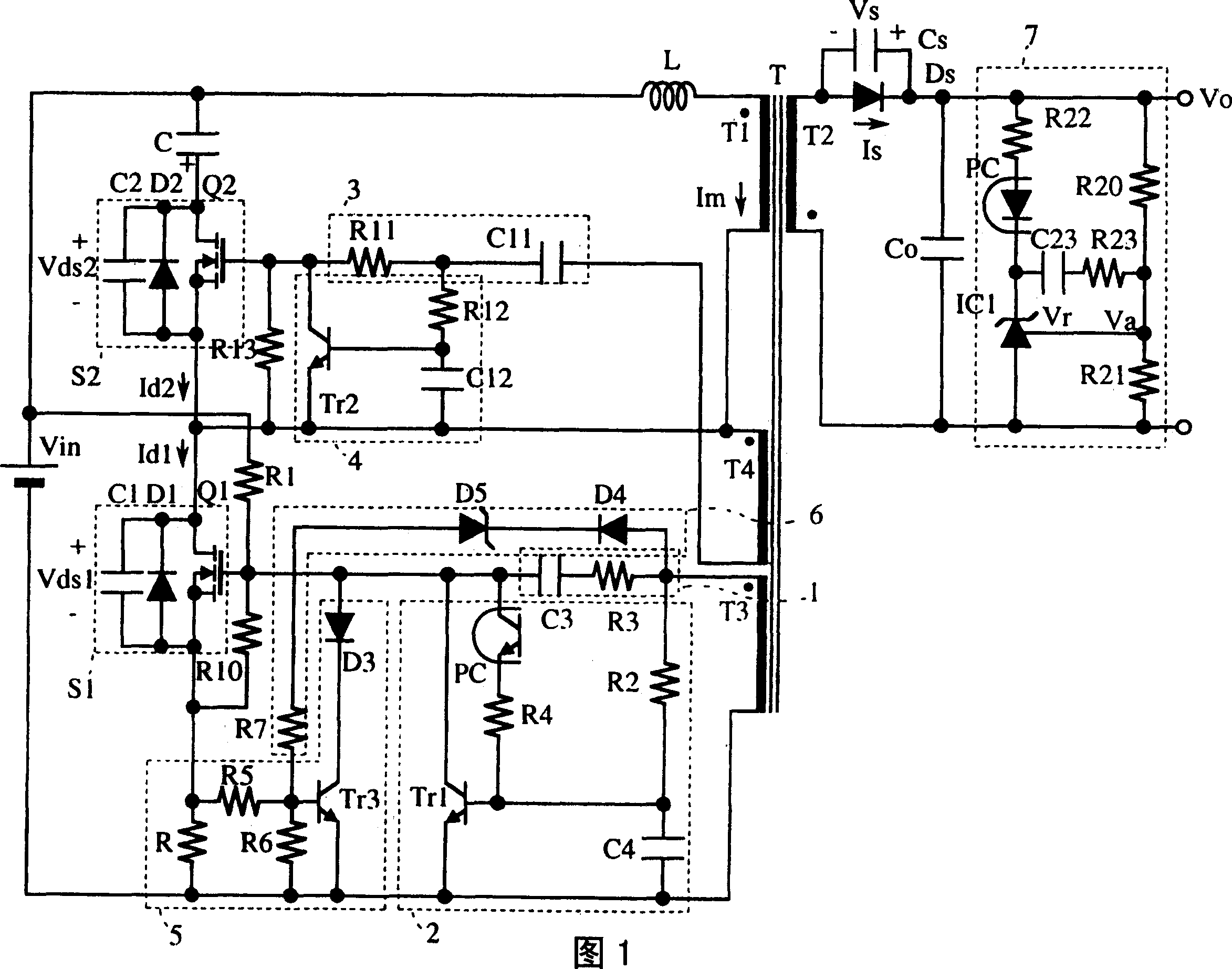
[0086] Fig. 1 is a circuit diagram of a switching power supply device according to Embodiment 1 of the present invention.

[0087] At the primary of the transformer T, in the series circuit of its primary coil T1 and the inductor L, a first switching circuit S1 and the input power supply Vin are connected in series, and the series circuit of the second switching circuit S2 and the capacitor C is connected in parallel to the primary coil T1 and the inductance L in the series circuit. In addition, a rectifying and smoothing circuit including a rectifying element Ds is connected to the secondary winding T2 of the transformer T.

[0088] The first switching circuit S1 is composed of a first switching element Q1, a first diode D1, and a first capacitor C1 connected in parallel. The second switching circuit S2 is composed of a second switching element Q2, a second diode D2, and a second capacitor C2 connected in parallel.

[0089] On the transformer T, a first drive coil T3 and a second...


PUM


Abstract

A switching power supply unit includes first and second switching elements which are alternately turned on/off so as to perform self-excited oscillation. An inductor and a capacitor resonate during an OFF-period of the first switching element. After the second switching element is turned on, a resonance current applied to a series circuit including the second switching element and the indictor is interrupted before energy is completely emitted from a secondary winding. Accordingly, a voltage is generated at the inductor and a voltage at a transformer is reversed so as to turn off the second switching element accordingly. Therefore, it can be attained effective switching electrical source, compressed and light element and low-cost.

Description

technical field [0001] The invention relates to a switching device for providing a DC stabilized power supply, in particular to a switching power supply device which enables two switching elements to be turned on / off alternately, self-excited oscillation, and works in a continuous current mode. Background technique [0002] For example, Japanese Patent Laid-Open No. 11-187664 describes a switching power supply device in which a first switching element Q1 and a second switching element Q2 are connected to the primary side of a transformer, and a switch is provided to sandwich the first and second switching elements Q1 and Q2. During the period when both are off, the switch control circuit that is turned on / off alternately, and during the conduction period of the first switch element Q1, energy is stored in the primary coil and the inductance L, and during the off period of the first switch element Q1 In this process, the energy is released from the secondary coil, so that the...

Claims


Application Information

Patent Timeline
IPC IPC(8): H02M3/28H02M3/338
CPCH02M3/3385H02M3/28
Inventor 细谷达也竹村博
Owner MURATA MFG CO LTD
Why Eureka
Try Eureka