Frequency distribution plan having shared signals on left and right with filtration and transmission system thereof

A frequency allocation and scheme technology, applied in the direction of wavelength division multiplexing system, electromagnetic wave transmission system, transmission system, etc.

Inactive Publication Date: 2003-03-26
ALCATEL LUCENT SAS
View PDF0 Cites 0 Cited by
  • Summary
  • Abstract
  • Description
  • Claims
  • Application Information

AI Technical Summary

Problems solved by technology

Improving bandwidth ut

Method used


Image

  • Frequency distribution plan having shared signals on left and right with filtration and transmission system thereof
  • Frequency distribution plan having shared signals on left and right with filtration and transmission system thereof
  • Frequency distribution plan having shared signals on left and right with filtration and transmission system thereof

Examples


Embodiment Construction

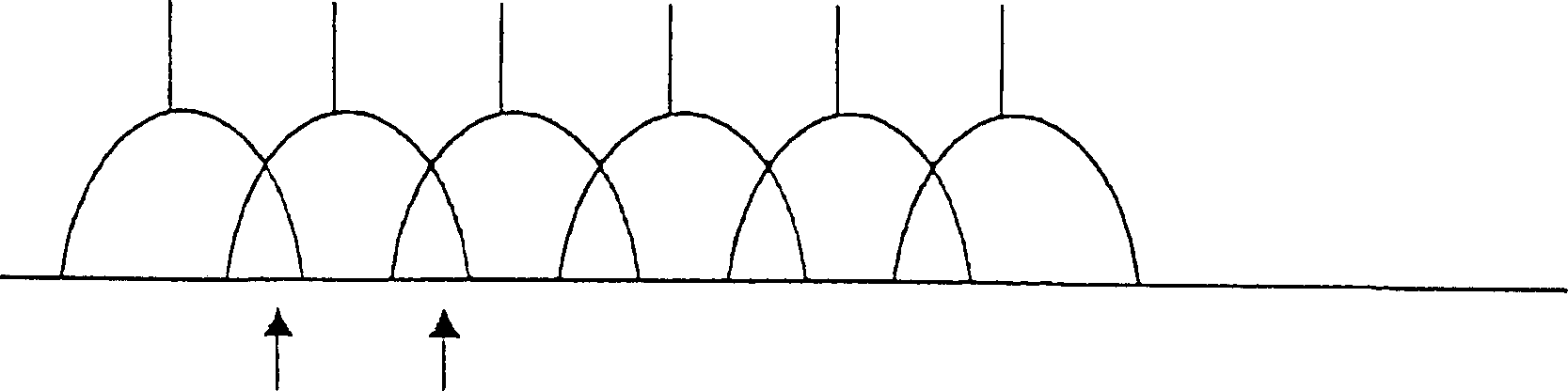
[0020] The NRZ signal spectrum is symmetrical to the carrier frequency of the wavelength channel. exist figure 1 In , the straight line represents the carrier. The left and right bands of the signal contain the same information. In the area of ​​overlap indicated by the arrows, it is no longer possible to unambiguously distinguish the information of one channel from the information of adjacent channels. As the channel spacing decreases as in DWDM (Dense Wavelength Division Multiplexing), the overlapping area increases.

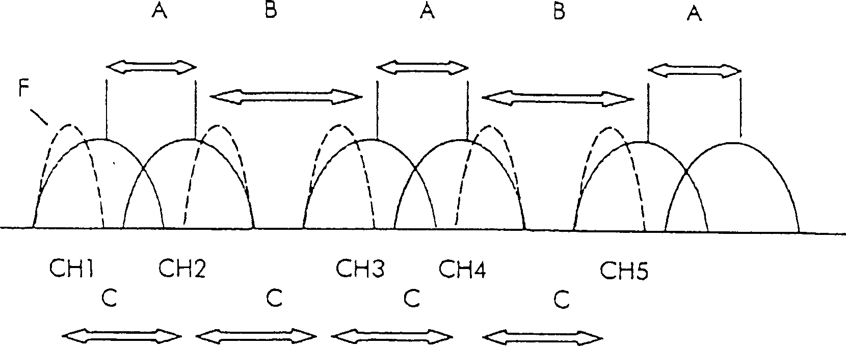
[0021] figure 2 The non-equidistant channel distribution is shown. Interval A separates the first two channels CH1 and CH2. Next, CH2 is separated from the next channel CH3 by a gap B. Then, channel pairs are transmitted, and the interval between each channel pair is larger than the interval within the channel pair. The filter function F filters the left band of channel CH1 and the right band of channel CH2. In addition, the left band of CH3 and the r...


PUM


Abstract

The invention shows a frequency allocation scheme for optical channels transmitted via a WDM transmission line with alternating left side and right side filtering for adjacent channels, with alternating channel spacing of A and B, where A H04B 10/04 H04B 10/06 H04B 10/10 4 5 8 2002/2/11 1405996 2003/3/26 1198412 2005/4/20 2005/4/20 2005/4/20 Alcatel France Sybastin Biguo Yan Frigenac Virfride Edler wu lili 11256 European 2001/2/16 01440033.7

Description

technical field [0001] The invention relates to the field of transmitting digital data using optical means. More specifically, the invention relates to the process of transmitting at high bit rates over long distance optical links. [0002] More specifically, the present invention relates to a frequency allocation scheme for multiplexing a set of optical channels (each having a specific carrier frequency) using a wavelength division multiplexing process and a polarization division multiplexing process. Background technique [0003] The invention also relates to a transmission system with a transmitter functional block comprising a light source with a modulator, possibly a polarizer and a wavelength multiplexer, and a receiver functional block comprising One or more polarization demultiplexers, wavelength demultiplexers, filters and receivers. [0004] This transmission scheme uses an optical transmitter connected to an optical receiver via a fiber optic link. The transmit...

Claims


Application Information

Patent Timeline
IPC IPC(8): H04J14/02H04J14/06
CPCH04J14/0224H04J14/06
Inventor 赛巴斯蒂恩·比果延·弗莱格纳克威尔弗莱德·艾德勒
Owner ALCATEL LUCENT SAS
Why Eureka
Try Eureka