

Method and apparatus for pressing component
A workpiece and equipment technology, applied in the field of improvement of pressed workpieces, can solve problems such as reduced output, long heating time, low thermal conductivity, etc.
- Summary
- Abstract
- Description
- Claims
- Application Information
AI Technical Summary
Problems solved by technology
Method used
Image

Examples
no. 1 example
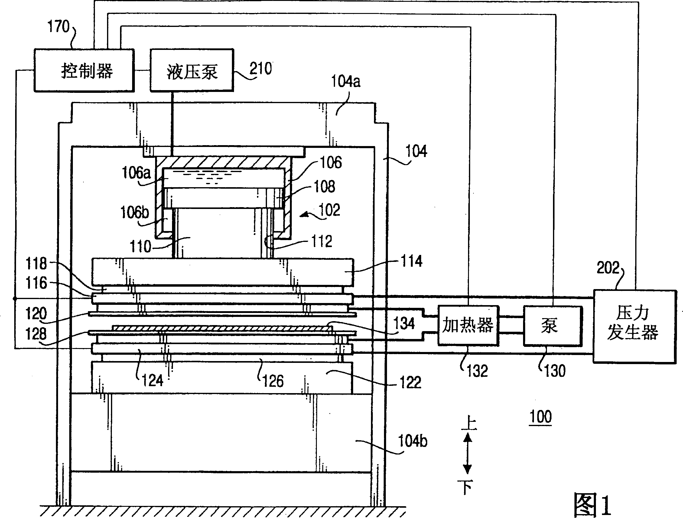
[0053] FIG. 1 schematically shows a structural view of a pressing apparatus 100 according to a first embodiment of the present invention.
[0054] The pressing apparatus 100 includes a piston-cylinder mechanism 102 mounted on a top plate 104 a of a frame 104 . The piston-cylinder mechanism 102 includes a cylinder 106 and a piston 108 located within the cylinder 106 and extending up and down the inner wall of the cylinder 106 . A through hole 112 is opened at the bottom of the cylinder 106 . The piston rod 110 is mounted on the bottom of the piston 108 and moves up and down together with the piston 108 .
[0055] The internal space of the cylinder 106 is divided into an upper space 106a and a lower space 106b by the piston 108 . Both the upper space 106a and the lower space 106b are filled with hydraulic oil. The upper and lower spaces 106 a , 106 b are connected to a hydraulic pump 210 , and the hydraulic pump 210 is driven under the control of the controller 170 . The hyd...
no. 2 example
[0092] Next, a pressing apparatus according to a second embodiment of the present invention will be described. It should be noted that in this embodiment and the following embodiments, those components that are substantially the same as those described in the first embodiment are still denoted by the same reference numerals.
[0093] FIG. 5 shows the structure of a pressing apparatus 300 according to a second embodiment of the present invention. The structure and operation of the pressing apparatus 300 according to the second embodiment of the present invention are the same as those of the first embodiment, except that the structures of upper and lower heating platens 302, 304 and upper and lower platen covers 306, 308 are different. In particular, the upper and lower deck covers 306 , 308 differ from the first embodiment in that they also include a backing plate 310 instead of the frame 190 .
[0094] Figure 6 is a horizontal cross-sectional view of the upper heated platen...
no. 3 example
[0106] FIG. 9 schematically shows the structure of a pressing device 400 according to a third embodiment of the present invention, which is a modification of the pressing device 300 of the second embodiment of the present invention.
[0107]The pressing apparatus 400 according to the third embodiment is different from the pressing apparatus 300 of the second embodiment in that the lower surface of the upper heating platen 302 and the upper surface of the lower heating platen 304 are covered by a top plate 402 and a carrier plate 404, respectively, while Instead of being covered by upper and lower deck covers 306, 308, they are all made of stainless steel. Also, the pressing apparatus 400 according to the third embodiment includes two mat members 406 and one or more intermediate plates 408 . Each intermediate plate is made of stainless steel and has a mirror-polished surface with a roughness within a few microns. The pressing apparatus 400 according to the third embodiment is ...
PUM
| Property | Measurement | Unit |
|---|---|---|
| thickness | aaaaa | aaaaa |
| thickness | aaaaa | aaaaa |
Abstract
Description
Claims
Application Information