
Method for detecting deformation of underwater engineering structure based on fibre-optic gyro technique and its device

A technology for technical inspection and underwater engineering, which is applied to devices using optical methods, measuring devices, and optical devices. effect of implementation

Inactive Publication Date: 2003-04-23
WUHAN UNIV OF TECH
View PDF0 Cites 19 Cited by
  • Summary
  • Abstract
  • Description
  • Claims
  • Application Information

AI Technical Summary

Problems solved by technology

Due to the limitations of actual observation conditions, there are great problems in the implementation of these traditional measurement methods for large underwater engineering structures, among which the determination of the reference point is the biggest difficulty. For example, in the measurement of dams and underwater pipelines, underwater search The reference point is quite difficult; secondly, the traditional method cannot measure continuously and accurately at all, and the value of other points can only be calculated from the measured value of certain points; in addition, the erection of the instrument underwater is also one of the difficulties

Method used


Image

  • Method for detecting deformation of underwater engineering structure based on fibre-optic gyro technique and its device
  • Method for detecting deformation of underwater engineering structure based on fibre-optic gyro technique and its device
  • Method for detecting deformation of underwater engineering structure based on fibre-optic gyro technique and its device

Examples


Embodiment Construction

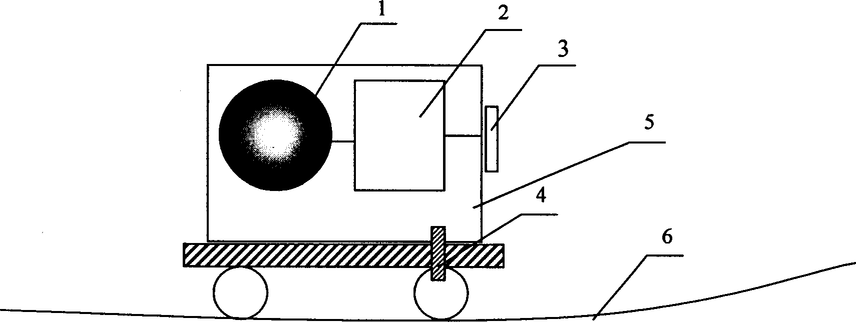
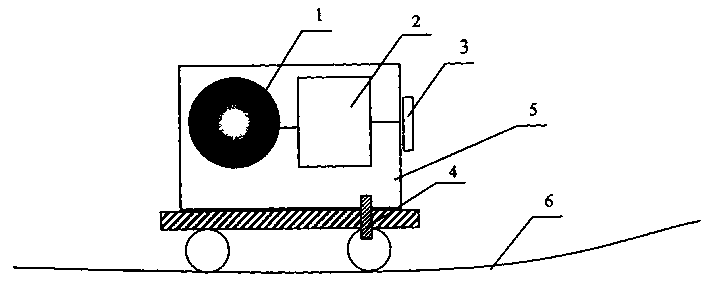
[0017] The basic composition of the device for detecting deformation of underwater engineering structures based on fiber optic gyroscope technology is as follows: figure 1 shown. The device includes a fiber optic gyroscope 1 , a signal receiving and storing unit 2 , a computer interface 3 , a linear velocity sensor 4 and a casing 5 . The fiber optic gyroscope 1, the signal receiving storage unit 2, the computer interface 3, and the linear velocity sensor 4 are all installed in a waterproof airtight casing 5, and the casing 5 can move along the measured object 6 under the drive of external force, and the measurement data is passed through the computer interface 3 sent to a computer for data processing. The shell 5 has good sealing, waterproof and anti-interference performance, and can adapt to the harsh underwater environment.

[0018] Determine the parameters such as the inclination angle of the starting point before the measurement. During the measurement, the device needs...


PUM


Abstract

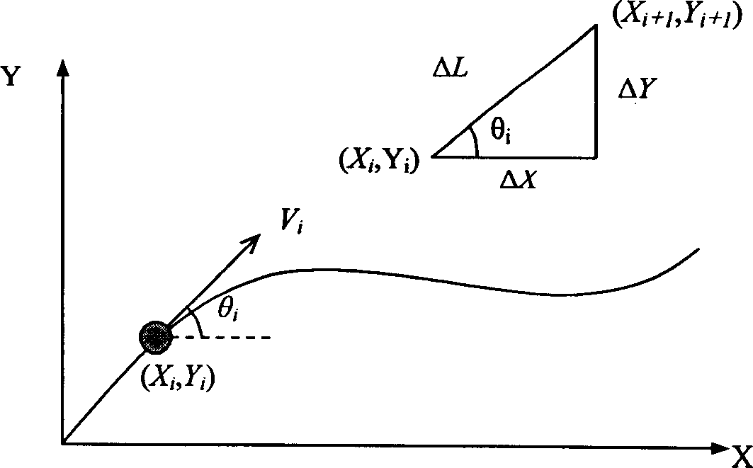
The present invention relates to a method for detecting deformation of underwater engineering structure based on fiber-optical gyro technology and its equipment. It is formed from fibre-optical gyroscope, line speed sensor and signal receiving and storing unit which are packaged in a closed container. Said method and its equipment utilize the characteristics of the fiber-optical gyroscope sensingangle speed, said closed container can be pulled and moved along tested object, and the data measured by said gyroscope and line speed sensor can be processed so as to obtain its I-D or 3-D movement trace by means of calculating according to the formula, i.e. I-D or 3-D deflection and deformation of tested object.

Description

technical field [0001] The invention relates to a method and a device for detecting deformation of an underwater engineering structure, in particular to a method and a device for detecting deformation of an underwater engineering structure based on an optical fiber gyro technology. Background technique [0002] In many large-scale underwater engineering structures, important information can be obtained by monitoring the deformation of the engineering structure. For example, the maximum deflection value of the panel can be used as a design analogy index for the deformation control of the panel dam. The shape change of the underwater pipeline is an important indicator for evaluating the pipeline work. parameter. Due to the limitations of actual observation conditions, there are great problems in the implementation of these traditional measurement methods for large underwater engineering structures, among which the determination of the reference point is the biggest difficulty....

Claims


Application Information

Patent Timeline
Patent Type & Authority Applications(China)
IPC IPC(8): G01B11/16G01C19/00G01P3/36
Inventor 姜德生王立新胡文彬戴珩梁磊
Owner WUHAN UNIV OF TECH
Learn More