Multifunctional thermodynamic simulated experiment machine

A thermal simulation and experimental machine technology, applied in teaching models, educational appliances, instruments, etc., to increase rigidity, improve test accuracy, and reduce frame deformation

Inactive Publication Date: 2003-04-23
NORTHEASTERN UNIV
View PDF0 Cites 17 Cited by
  • Summary
  • Abstract
  • Description
  • Claims
  • Application Information

AI Technical Summary

Problems solved by technology

[0003] Aiming at the problems existing in the existing thermal simulation test machi

Method used


Image

  • Multifunctional thermodynamic simulated experiment machine
  • Multifunctional thermodynamic simulated experiment machine
  • Multifunctional thermodynamic simulated experiment machine

Examples


Embodiment Construction

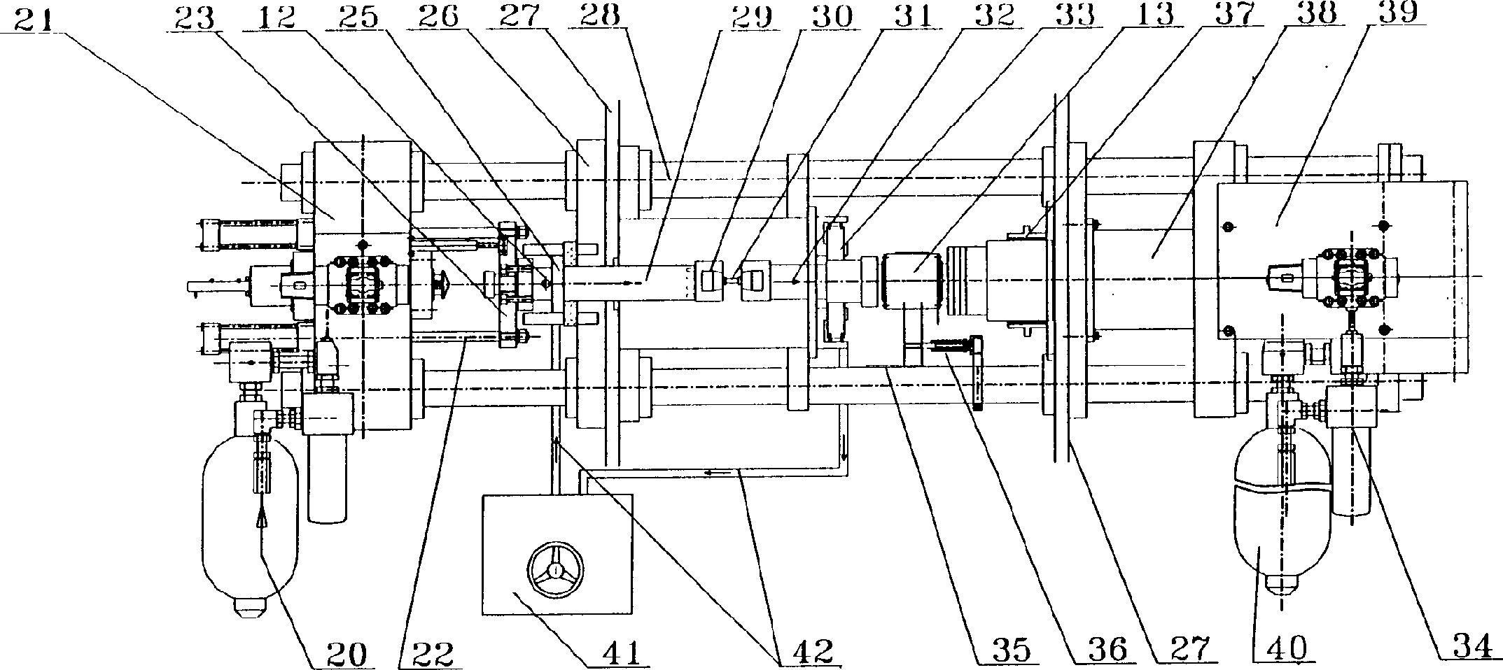
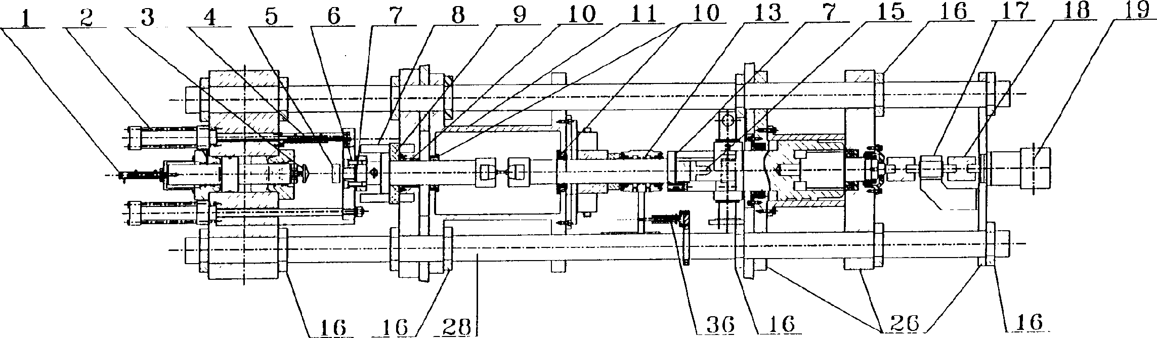
[0037] refer to figure 1 , figure 2 , The overall structure of the present invention is made up of parts such as two beams 28, main hydraulic cylinder 21, secondary hydraulic cylinder 39, left shaft 29, right shaft 32, operation box 11, test switching device 38, positioning beam 26 and support beam 27. The supporting beam 27 is supported on the ground by two sets of structural frames, and the structural frames including the beams 28 support the whole set of equipment. Crossbeam 28, four positioning beams 26, main hydraulic cylinder 21 and operation box 11 such as figure 1 The position shown in is tightly fixed into one body through a plurality of clamping rings 16 and is connected with the support structure frame through support beams 27, wherein two positioning beams 26, two cross beams 28 and the operation box 11 are directly connected with the support beams 27, in addition The two positioning beams 26 and the main hydraulic cylinder 21 are connected to the cross beam 28,...


PUM


Abstract

The multifunctional thermodynamic simulation experiment equipment is formed from cross beams, main and auxiliary hydraulic cylinders, shaft, operation box, test conversion device, force measuring device, electric conducting device, turning connector, hydraulic brake, positioning beam and supporting beam. Under the condition of no changing any component said invention can implement tension, compression and torsion experiments, and also can make tension-torsion composite stress deformation experiment.

Description

Technical field [0001] The invention belongs to physical simulation experiment equipment, in particular to a multifunctional thermal simulation experiment machine. Background technique [0002] Metal materials will produce a variety of physical and mechanical behaviors in continuous casting, pressure processing, heat treatment, welding and other thermal processing processes, as well as in the partial use of finished products; in order to improve processing technology, reduce costs, and improve product quality and performance, It is necessary to apply physical simulation technology to predict in advance; physical simulation is the reproduction of industrial processes on experimental equipment, mainly to test the stress-strain relationship, dynamic, sub-dynamic and static reconstruction of materials under different deformation temperatures, deformation speeds and deformation states. Crystallization laws and the correlation between microstructure and mechanical properties, so t...

Claims


Application Information

Patent Timeline
IPC IPC(8): G09B25/02
Inventor 王国栋刘相华骆宗安王黎筠岳发张殿华苏海龙
Owner NORTHEASTERN UNIV
Why Eureka
Try Eureka