

Automatically starting paper cutter
An automatic start and paper shredding technology, which is applied in the direction of grain processing, etc., can solve the problems of no space, automatic start failure, insufficient upward range of shrapnel 14, etc.
- Summary
- Abstract
- Description
- Claims
- Application Information
AI Technical Summary
Problems solved by technology
Method used
Image

Examples
Embodiment Construction
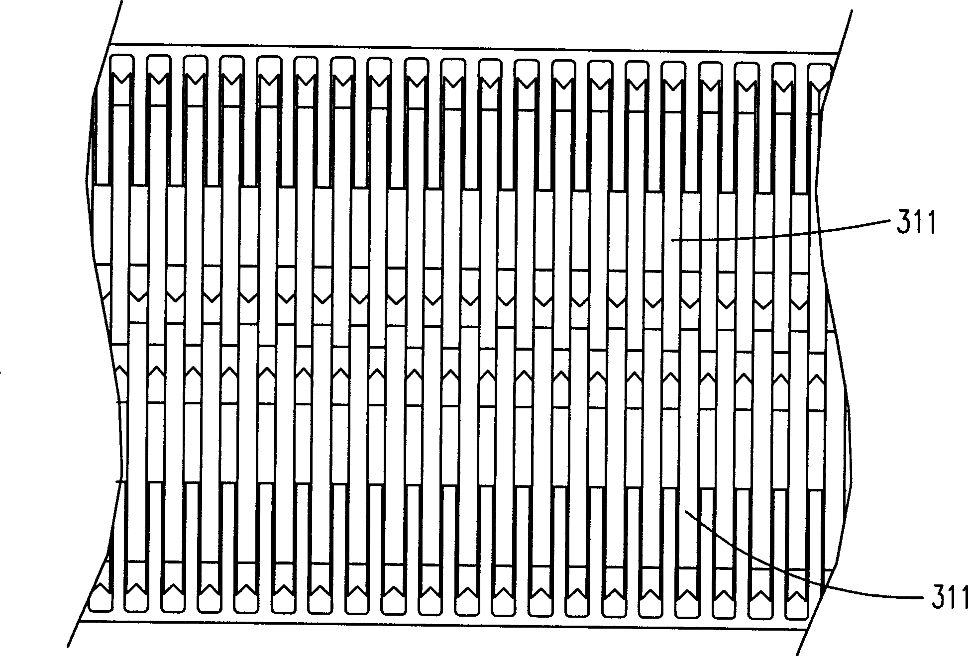
[0016] Please refer to Fig. 4, it is a schematic view of the structure of a preferred embodiment of the paper shredding device of the present invention, because the present invention is aimed at the improvement of the automatic start and delay structure part, so it is suitable for conventional structures (such as image 3 ) is not much different from the paper shredding mechanism (consisting of the first shaft, the second shaft, multiple cutting blades, multiple gap paper guides) and the power source completed by the motor and other components are not disclosed in the figure middle. As can be clearly seen from the figure, the trigger of the present embodiment is completed by a lug 401 fixed on the connecting rod 40 and is located at the inlet end of the shredded paper passage 41, which can overcome the conventional image 3 There is no problem that there is space for the actuator to be arranged between the middle blades 311 . The protruding piece 401 is resisted by the paper ...
PUM
 Abstract
Description
Claims
Application Information