Oscillating fan without vibration
A fan and vibration elimination technology is applied in the field of electric fans to achieve the effects of small vibration, easy implementation, and beautiful appearance
- Summary
- Abstract
- Description
- Claims
- Application Information
AI Technical Summary
Problems solved by technology
Method used
Image

Examples
Embodiment 1
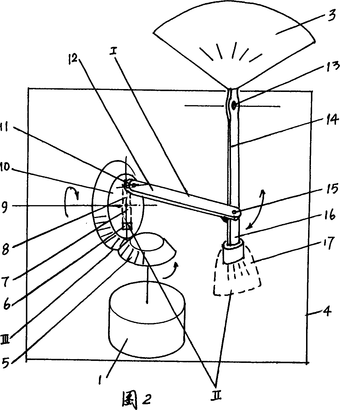
[0016] Referring to Fig. 2, this is an embodiment in which the connecting rod and the swing rod are connected by hinges according to the present invention. In this embodiment, the swing fan is mainly composed of a motor 1 , a transmission III, a linkage mechanism I, a balance device II, a casing, a base 4 and a fan blade 3 . The motor 1 is fixed on the shell and the base 4, the transmission III can be fixed with the motor 1, and can also be fixed with the shell and the base 4, the balance device II is installed on the linkage mechanism I, and the fan blade 3 is connected with the linkage mechanism I connected.
[0017] Link mechanism 1 of the present invention can be made up of crankshaft 8, connecting rod 12 and fork 14, and one end of connecting rod 12 links to each other with crankshaft 8 by hinge support 11, and the other end links to each other with fork 14 by fork hinge support 15, and swing link 14 and shell are hingedly connected with base 4.
[0018] Speed changer...
Embodiment 2
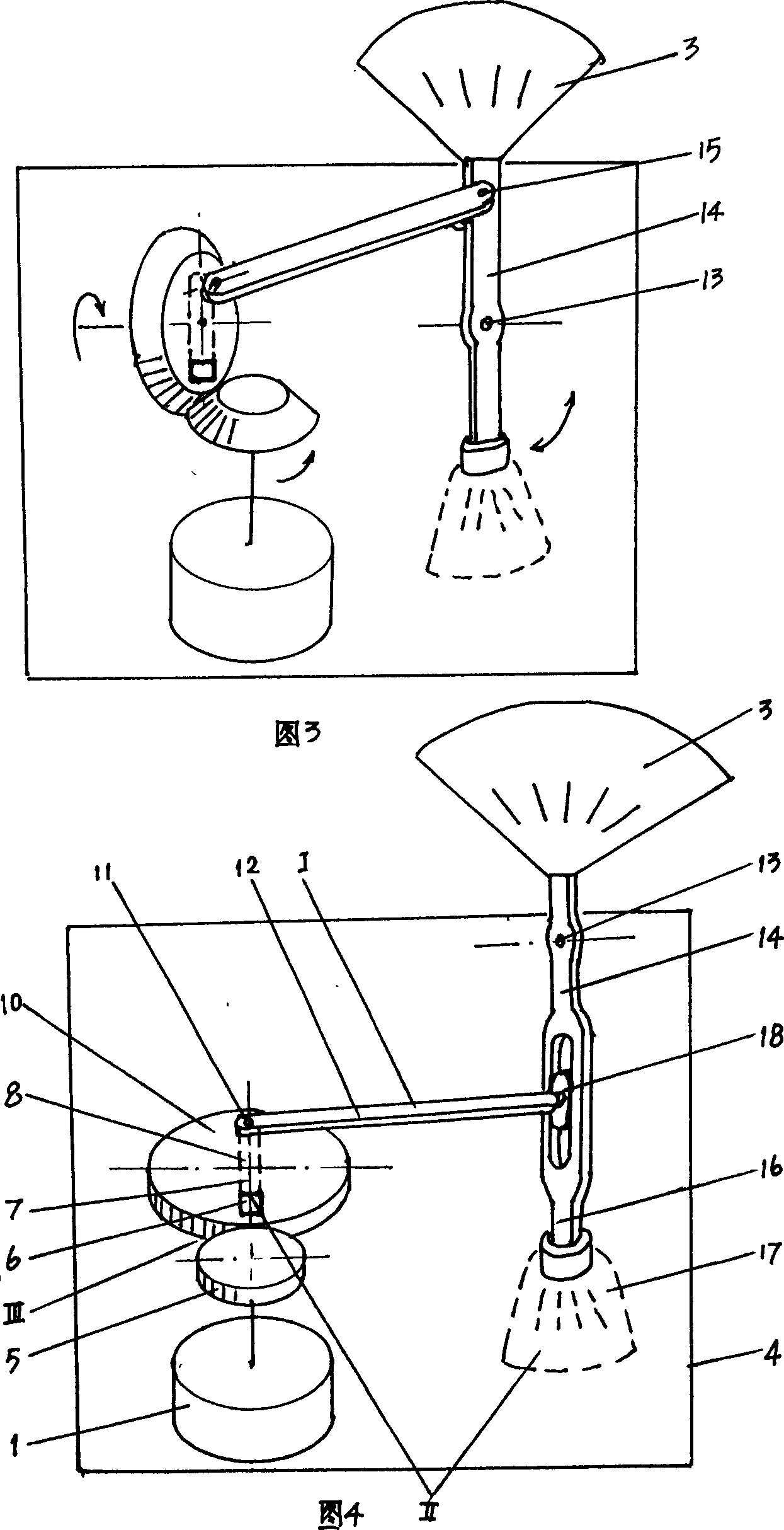
[0023] Referring to Fig. 4, this is an embodiment in which the connecting rod and the swing rod are connected through a slider in the present invention. In this embodiment, the swing fan is also made up of a motor 1, a speed changer III, a link mechanism I, a balancing device II, a casing, a base 4, and a fan blade 3, and the composition of the link mechanism I and the balancing device II are the same as those of the balancing device II. Embodiment 1 is the same. Only one end of the connecting rod 12 is connected with the crankshaft 8 through the hinged support 11 of the crankshaft, and the other end is connected with the fork 14 through the slide block 18 . With the swing shaft 13 of the swing link 14 as the boundary, the slider 18 can be on the same side of the fan blade 3 (see Figure 5 ), of course it can also be on the other side of the fan blade
[0024] Referring to Fig. 2 or Fig. 4, during use, when motor 1 rotates and forms required rotating speed by speed changer I...
PUM
 Abstract
Description
Claims
Application Information
 - R&D Engineer
- R&D Manager
- IP Professional
- Industry Leading Data Capabilities
- Powerful AI technology
- Patent DNA Extraction
Browse by: Latest US Patents, China's latest patents, Technical Efficacy Thesaurus, Application Domain, Technology Topic.
© 2024 PatSnap. All rights reserved.Legal|Privacy policy|Modern Slavery Act Transparency Statement|Sitemap