Dryer

A drying device and drying technology, which are applied in the drying of solid materials, non-progressive dryers, drying, etc., can solve the problems of inability to circulate drying and the drying process cannot be carried out smoothly, and achieve the effect of reducing resistance.

Inactive Publication Date: 2003-05-21
金井 正夫
View PDF0 Cites 3 Cited by
  • Summary
  • Abstract
  • Description
  • Claims
  • Application Information

AI Technical Summary

Problems solved by technology

The ascending channel of the object to be dried is blocked, which prevents circulation and drying, which may easily cause the drying process to fail to proceed smoothly.

Method used


Image

  • Dryer
  • Dryer
  • Dryer

Examples


Embodiment Construction

[0053] Embodiments of the invention

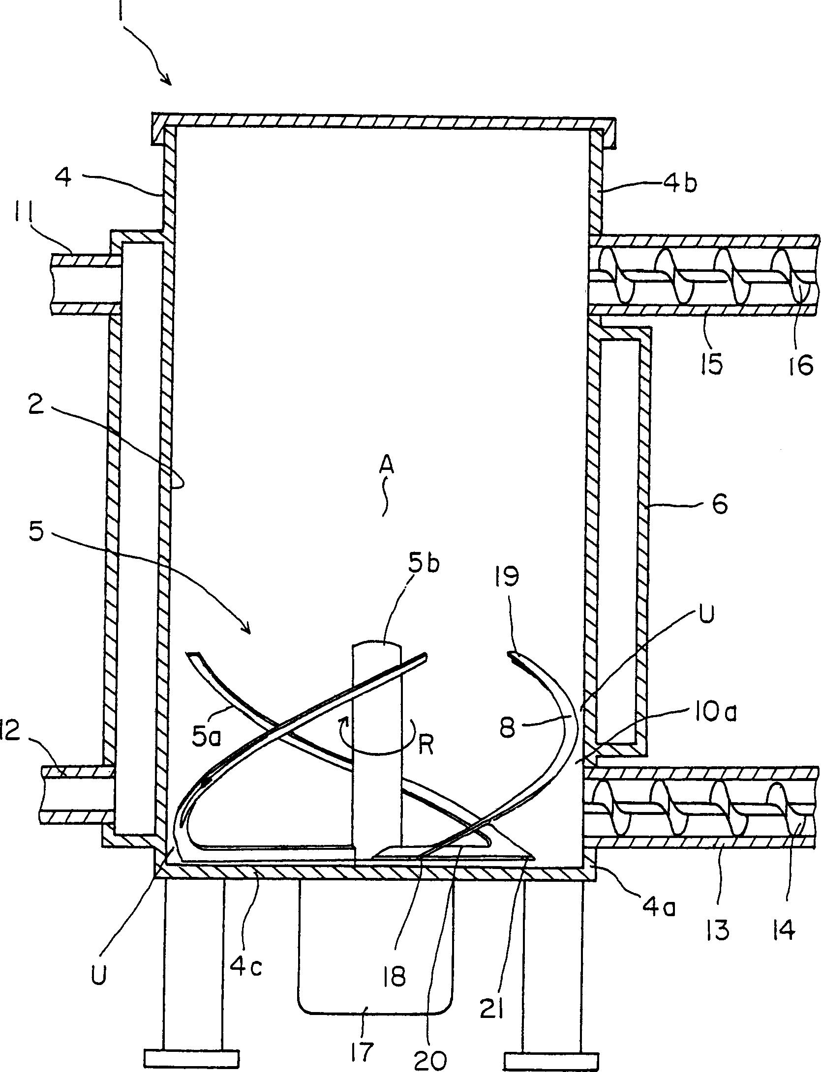
[0054] Embodiments of the present invention will be described in detail below with reference to the drawings. Figure 1 to Figure 8 It is the drying device 1 of the first embodiment. In the figure, 4 is a cylindrical drying tank, and its cylindrical inner wall is the heat transfer surface 2 of the drying device, and its function is to transfer the heat supplied by the heat transfer equipment to the object 3 to be dried. The above-mentioned heat transfer equipment refers to the jacket 6 located around the drying tank 4 and the boiler (not shown) connected to the jacket to send steam 7 to the jacket 6 . In addition, the jacket 6 is provided with a steam introduction part 11 for introducing the steam 7 into the jacket 6 and a steam discharge part 12 for discharging the steam 7 out of the jacket 6 .

[0055] The side wall at the bottom 4a of the above-mentioned drying tank 4 is connected with a dried material supply pipe 13, and the dried ma...


PUM


Abstract

The present invention provides a drying device of high drying efficiency by effectively using the whole heat transfer face without retention and biting of a dried object. In this drying device (1), a rotary winding blade (5) composed of a plurality of base blades (5a) is installed rotatably around a rotating shaft (5b) in a drying tank (4) formed with a heat transfer face (2). Each base blade (5a) has a flat face (8) of elongate shape extending obliquely upward from one end part (18) toward the other end part (19) in a reverse direction to a rotating direction R, and a clearance U is formed between an outer peripheral end 10a and the heat transfer face (2). The clearance U is formed to be gradually larger in the reverse direction to the rotating direction. One end part (18) of the flat face (8) is continuous with a scraping plate (20), and a projecting part (21) is provided in the rotating direction R from the outermost end part of the scraping plate (20).

Description

technical field [0001] The invention relates to a drying device which pushes the object to be dried to the heat transfer surface while rolling up the object to achieve the drying effect. Background technique [0002] As we all know, there are many kinds of drying equipment for drying liquid, fluid, semi-fluid or powder, granular and other dried objects. [0003] For example, the present applicant previously disclosed the drying apparatuses in the publications such as JP-3-19501 and JP-5-64692. This drying device consists of a cylindrical drying tank used to put in the dried object, a cylindrical drying tank inner wall heat transfer surface that transfers the heat source to the dried object, and a heat transfer surface located around the drying tank. The heat-supplying heat transfer equipment and a vertical helical rotating blade which is arranged in the above-mentioned drying tank and can rotate is composed of a plane that can make the dried object rise after being loaded. ...

Claims


Application Information

Patent Timeline
Patent Type & Authority Applications(China)
IPC IPC(8): F26B11/14C02F11/12F26B3/24F26B11/12F26B17/34F26B25/04
Inventor 金井正夫
Owner 金井 正夫
Why Eureka
Try Eureka