Ultrasonic diagnosis device and operation apparatus

A technology for ultrasonic diagnosis and operating equipment, which is applied in the directions of sonic diagnosis, infrasound diagnosis, ultrasonic/sonic/infrasonic diagnosis, etc., which can solve the problems of the operator enduring the physical burden, not considering the operator's environment, wasting time, etc.

Inactive Publication Date: 2003-05-28
KK TOSHIBA
View PDF1 Cites 22 Cited by
  • Summary
  • Abstract
  • Description
  • Claims
  • Application Information

AI Technical Summary

Problems solved by technology

[0007] However, in ultrasonography, especially in the observation of hemodynamic characteristics using a contrast agent, operators such as doctors and technicians need to touch the subject (patient) with the ultrasound probe so as to remain in the same area of ​​interest, and as a result, in this The switching operation of the device under the circumstances requires the operator to bear the burden of the body
Also, because the operator needs to gaze at switches on control boards (such as consoles and control panels) in order to perform switching operations, the target area of ​​interest is often lost and requires readjustment
it means wasting time
[0008] The above-mentioned ultrasonic diagnostic device with a workflow system simplifies the complex series of switching operations, but its invention does not take into account the above-mentioned operator's environment, and it still requires switching operations on a part of the main frame of the device
Regarding this, there is still no change in conventional technology

Method used


Image

  • Ultrasonic diagnosis device and operation apparatus
  • Ultrasonic diagnosis device and operation apparatus
  • Ultrasonic diagnosis device and operation apparatus

Examples


no. 1 example

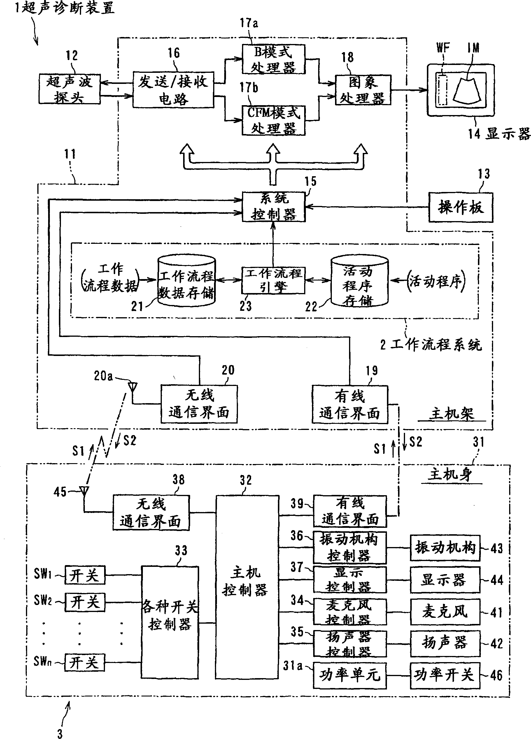
[0044] figure 1 The medical imaging diagnostic system shown 1 includes, in addition to the ultrasonic diagnostic device 1 as the main form, there is also a workflow system (WFS) 2 installed on the ultrasonic diagnostic device, and the operation of the ultrasonic diagnostic device 1 can be operated by remote control equipment3.

[0045] like figure 1 As shown, the hardware of the ultrasonic diagnostic apparatus 1 is composed of the following: a main frame 11 , an ultrasonic probe 12 , an operation panel 13 and a monitor 14 connected to the main frame 11 . The operation panel 13 is equipped with input devices such as switches, buttons, keyboard, trackball, and mouse.

[0046] The ultrasound probe 12 - which is responsible for transmitting and receiving ultrasound signals from and to the patient - includes piezoelectric transducers made of piezoelectric ceramics or the like as electromechanical bidirectional conversion elements. For example, a plurality of piezoelectric transd...

no. 2 example

[0093] refer to Figure 13 to Figure 15 , an ultrasonic diagnostic apparatus and an operating device according to a second embodiment of the present invention will be described.

[0094] Figure 13 to Figure 15 An example of a further portable operating device 3 is shown. The operating device 3 of this example includes a main body 31 having a rectangular shape, five switches SW11 to SW15 are prepared on the flat surface of the front, two switches SW16, SW17 are located on the left side surface, and one switch SW18 is located on the back surface. , in order to hold comfortably, a convex portion at the center and two concave portions at both sides of the convex portion are formed according to the shape of the hand.

[0095] Wherein, the switch SW11 located at the upper front of the device has the joint function of the switches SW1, SW2 and SW3 of the aforementioned embodiments, and includes a push-type execution button to determine such as an active item, and a direction key t...

no. 3 example

[0105] refer to Figure 16 , an ultrasonic diagnostic apparatus and an operating device according to a third embodiment of the present invention will be described.

[0106] Figure 16 An example of a stationary operating device 3 is shown. The operating device of this example includes a main body 31 having an oval shape. The operating device 3 is equipped with an unshown antenna portion (communication window) 45 on the side surface of the upper part, a speaker 42 at the lower part of the front, and a display (indicator) 44 ( Figure 16 "IASSIST" for WFS in execution, "Imaging" for normality check), and various switches SW21 to 29 similar to the previous embodiment.

[0107] The switch SW21 in the middle left part of the front is an execution button and is used to determine menus, etc., and has the same function as the switch SW1 of the foregoing embodiment. Similarly, the switch SW23 on the middle right is an arrow key used to transfer the WFS menu horizontally and vertica...


PUM


Abstract

An ultrasonic diagnostic apparatus comprises: an operation device which is configured to communicate with a main frame connected to an ultrasonic probe and which an operator of the main frame and the ultrasonic probe may carry and; a system controller to execute a workflow system which switches the operation of the main frame by sequentially executing a plurality of execution items (activities), which is executed by operation of the main frame, according to the work procedure (workflow protocol) predetermining the execution sequence of execution items, and alters the sequence of the execution items in compliance with the operation of the operation device.

Description

technical field [0001] The present invention relates to an ultrasonic diagnostic device and its operating equipment. More specifically, the present invention relates to the inventive design of a dedicated, suitable input device for a workflow system that supports operations during detection and diagnosis. Background technique [0002] Ultrasonic signals have been used clinically in various fields, one of which is in ultrasonic diagnostic devices. Ultrasonic diagnostic devices need to receive and transmit image signals from and to subjects through transmission and reception of ultrasonic signals, and are used in various modes using non-invasive signals. A typical type of ultrasonic diagnostic apparatus generates tomographic images of living soft tissues by using ultrasonic pulse reflection images. This imaging method is non-invasive and produces tomographic images of tissue. Compared with other medical forms such as X-ray diagnostic imaging, X-ray CT imaging, MRI and nucle...

Claims


Application Information

Patent Timeline
Patent Type & Authority Applications(China)
IPC IPC(8): A61B8/14A61B5/00A61B8/00A61B8/06A61B8/08
CPCY10S128/922A61B5/0002G01S7/52098A61B8/00
Inventor 小笠原洋一神山直久佐野昭洋
Owner KK TOSHIBA
Why Eureka
Try Eureka