Exhaust valve of sealed compressor

A technology of discharge valve and compressor, applied in mechanical equipment, machine/engine, liquid variable-capacity machinery, etc., can solve problems such as difficulty in manufacturing and assembling, increase in compressor noise, complex shape and structure, etc.

Inactive Publication Date: 2003-05-28
SAMSUNG GWANGJU ELECTRONICS CO LTD
View PDF0 Cites 5 Cited by
  • Summary
  • Abstract
  • Description
  • Claims
  • Application Information

AI Technical Summary

Problems solved by technology

When cylinder 6 is over-pressurized, more energy is required to drive rotor 2, reducing the operating efficiency of the compressor
[0014] Another problem is that the reed valve 13 constantly hits the top surface of the discharge hole 12 under the elastic force of the reed valve 13 and the brake 14, and the piston 5 will also generate a discharge force during the suction stroke, which will increase the work of the compressor noise
[0015] In addition, the discharge valve 10 is composed of many components, the shape and structure are complex, and it is difficult to manufacture and assemble

Method used


Image

  • Exhaust valve of sealed compressor
  • Exhaust valve of sealed compressor
  • Exhaust valve of sealed compressor

Examples


Embodiment Construction

[0033] Hereinafter, the preferred embodiments of the present invention will be described in detail with reference to the accompanying drawings.

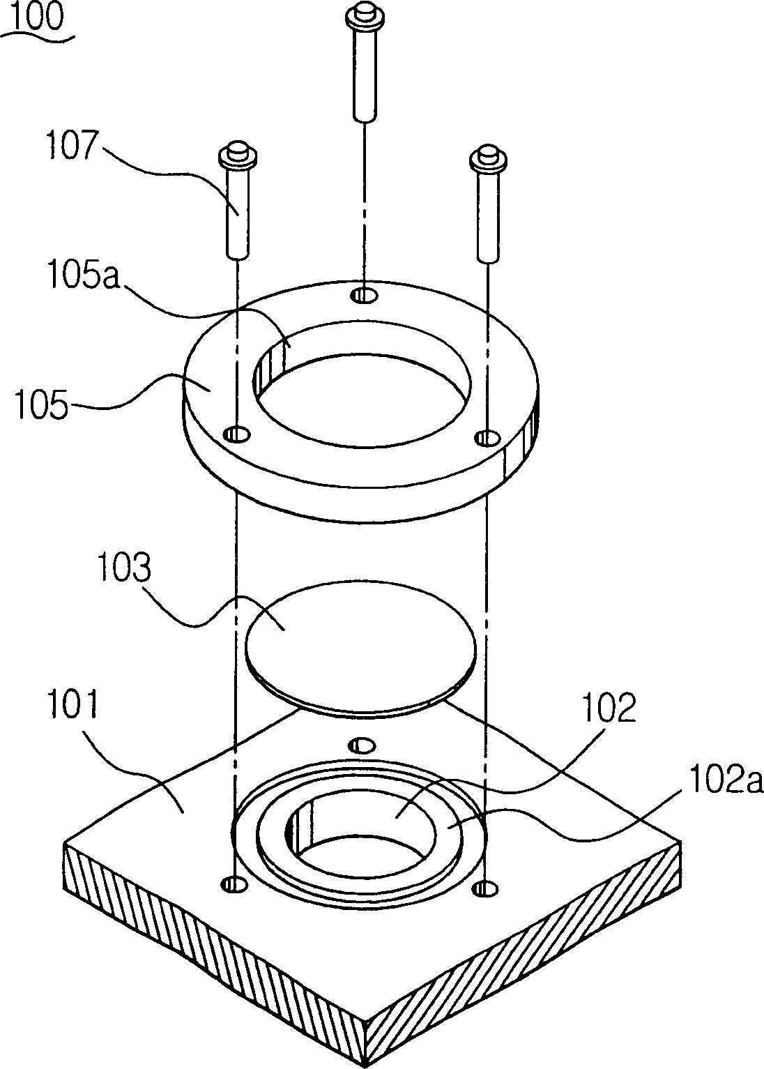
[0034] refer to Figure 3-5B , The hermetic compressor 100 according to the first embodiment of the present invention includes a valve plate 101 , a plate valve 103 , a stopper 105 and some guide pins 107 .

[0035] A valve plate 101 disposed on the cylinder head has a discharge hole 102 for discharging refrigerant and a suction hole (not shown) for sucking refrigerant into the compression chamber. As shown, the seat 102A is positioned on top of the discharge hole 102 so that the plate valve 103 can effectively close the discharge hole 102 .

[0036] The plate valve 103 for closing the discharge hole 102 is located on the top of the discharge hole 102, and its weight helps to compress the refrigerant when the discharge stroke closes the discharge hole, and when the pressure in the cylinder exceeds the weight of the plate valve, the ...


PUM


Abstract

A discharge valve of a hermetic compressor includes a valve plate disposed on a cylinder head that sucks and discharges refrigerant according to reciprocal movement of a piston, and the discharge valve having a discharge hole formed therein through which refrigerant is discharged, a disc valve disposed adjacent the discharge hole of the valve plate, the disc valve being raised or lowered by the reciprocal movement of the piston, and a stopper disposed above the disc valve, for guiding the raising and lowering of the disc valve and also for limiting the height to which the disc valve may be raised. The compressor is not subject to overload or over pressurization that may otherwise result from the elastic force of the valve, and as a result, compression efficiency is increased, while noise is decreased.

Description

technical field [0001] The present invention relates generally to hermetic compressors; more particularly, to discharge valves installed in cylinder heads for discharging compressed refrigerant. Background technique [0002] In general, hermetic compressors are used to compress refrigerants in devices that use refrigerants such as air conditioners and refrigerators. [0003] figure 1 The common hermetic compressor shown includes a stator 1 , a rotor 2 rotating in the stator 1 , a crankshaft 3 rotating with the rotor 2 , and a piston 5 connected to the crankshaft 3 . The connecting rod 4 reciprocates linearly with the rotation of the crankshaft 3 . The cylinder block 6 forms a compression chamber 6B, and is used together with the valve assembly 7 and the piston 5 installed in the cylinder head 6A to control the suction and discharge of refrigerant. [0004] The valve assembly 7 includes a suction valve and a discharge valve. During the suction stroke when the piston 5 move...

Claims


Application Information

Patent Timeline
Patent Type & Authority Applications(China)
IPC IPC(8): F04B39/10
CPCF04B39/1026Y10T137/7913Y10T137/7914Y10T137/7937F04B39/10
Inventor 李成泰
Owner SAMSUNG GWANGJU ELECTRONICS CO LTD
Why Eureka
Try Eureka