Positive- and negative-direction blowing-in and-out stilling -eliminating fan

A technology of air supply and exhaust, high-speed fan, applied in mechanical equipment, machine/engine, liquid fuel engine, etc., can solve problems such as surge, drop, equipment damage, etc., and achieve the effect of preventing equipment damage accidents

Inactive Publication Date: 2003-05-28
北京新安特风机有限公司
View PDF0 Cites 5 Cited by
  • Summary
  • Abstract
  • Description
  • Claims
  • Application Information

AI Technical Summary

Problems solved by technology

[0002] Existing fans, one-way or two-way positive and negative wind fans, especially axial flow and oblique fans, usually include a casing, a base on the casing, a motor inside the casing, and an impeller fixed on the shaft head of the motor. 1. The current collector located at the end of the casing can carry out forward and reverse air supply and exhaust in anti-corrosion and explosion-proof occasions. It has certain effects and is widely used, but there are also some shortcomings, such as

Method used


Image

  • Positive- and negative-direction blowing-in and-out stilling -eliminating fan
  • Positive- and negative-direction blowing-in and-out stilling -eliminating fan
  • Positive- and negative-direction blowing-in and-out stilling -eliminating fan

Examples


Embodiment Construction

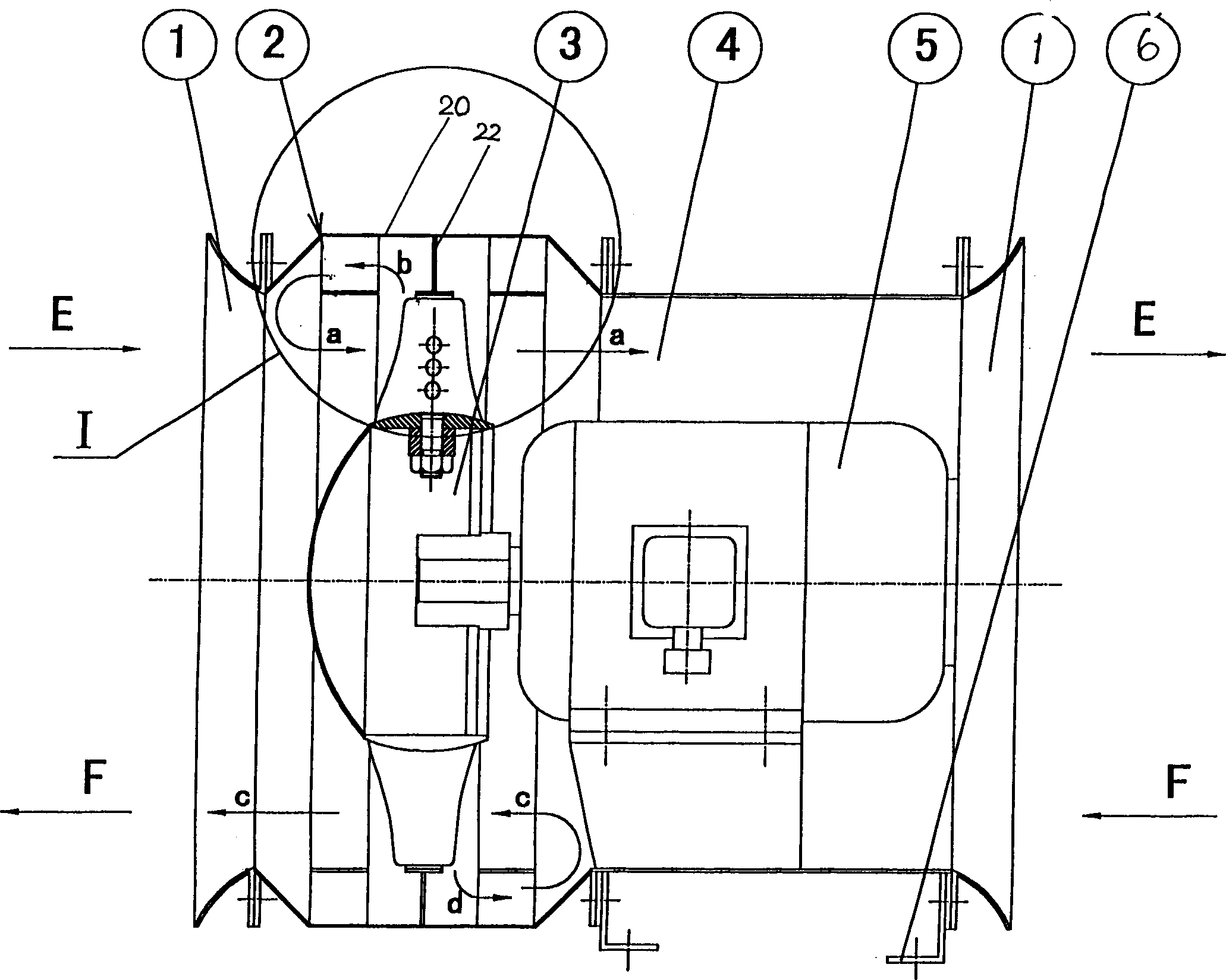
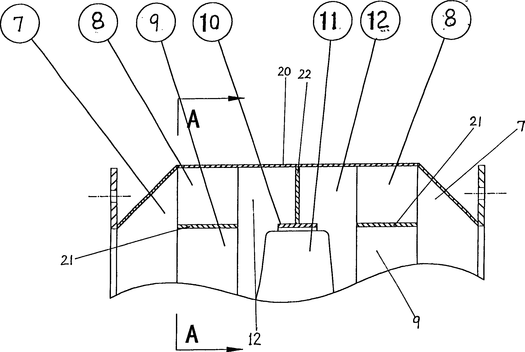
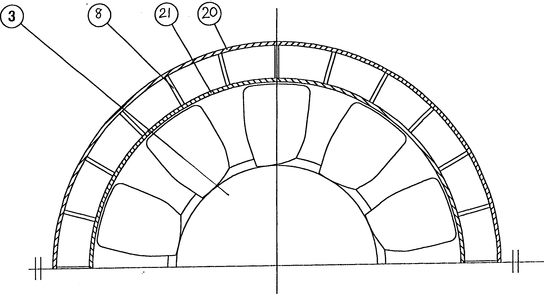
[0010] like figure 1 , figure 2 and image 3 As shown, the structure of the forward and reverse air supply and exhaust fan of the present invention includes a base 6 at the bottom of the base, a motor 5 inside the casing 4, an impeller 3 fixed on the motor shaft head and its The blade 11, the current collector 1 located at the end of the casing 4, its main feature is that a reflux device 2 protruding from the casing is provided outside the circumference of the impeller part, the middle section is a hollow cylinder; the two sides of the middle section are Hollow conical cone expansion tube 7; its inner end is fixedly connected with the inner end of the casing 4, and the present embodiment is connected by bolts through a flange; its outer end is fixedly connected with the inner end of the left collector 1, In this embodiment, the flanges are connected by bolts; the maximum outer diameter is greater than the outer diameter of the casing 4; In this way, the casing 4, the curre...


PUM


Abstract

A stall-eliminating blower for blowing or exhausting is composed of casing, motor, vane wheel and airflow collector, and is characterized by its additional reverse-flow unit, which can make the eddy flow caused by stall flow reversely back to main flow channel, so eliminating stall.

Description

technical field [0001] The invention relates to a fan, in particular to a forward and reverse air supply and exhaust vanishing speed fan used in any anti-corrosion and explosion-proof occasions. Background technique [0002] Existing fans, one-way or two-way positive and negative wind fans, especially axial flow and oblique fans, usually include a casing, a base on the casing, a motor inside the casing, and an impeller fixed on the shaft head of the motor. 1. The current collector located at the end of the casing can carry out forward and reverse air supply and exhaust in anti-corrosion and explosion-proof occasions. It has certain effects and is widely used, but there are also some shortcomings, such as the existing axial flow and diagonal flow fans The small flow area produces a stall condition and causes surge, so that the working range of the fan is relatively small, and the flow velocity of the gas along the radius and axial direction changes greatly. The flow at the r...

Claims


Application Information

Patent Timeline
IPC IPC(8): F04D29/54
Inventor 梁锡智沈光全
Owner 北京新安特风机有限公司
Why Eureka
Try Eureka