Flow regulating method and apparatus for gas

A flow adjustment device and flow adjustment technology, which are applied in the directions of flow control without auxiliary power, valve device, combustion method, etc., can solve the problems that the cross-sectional area cannot be changed, the flow rate is changed, and the flame length is changed.

Inactive Publication Date: 2003-06-11
THE JAPAN SMOKING ARTICLES CORP ASSOC
View PDF1 Cites 1 Cited by
  • Summary
  • Abstract
  • Description
  • Claims
  • Application Information

AI Technical Summary

Problems solved by technology

Although such a flow restricting member can limit the flow within a certain maximum range, since the micropores of the membrane maintain a certain size and the cross-sectional area cannot change, the flow cannot be changed from the outside. At the same time, due to changes in the external temperature When the gas pressure changes, the flow rate also changes, so that the flame length changes

Method used


Image

  • Flow regulating method and apparatus for gas
  • Flow regulating method and apparatus for gas
  • Flow regulating method and apparatus for gas

Examples


Embodiment 1

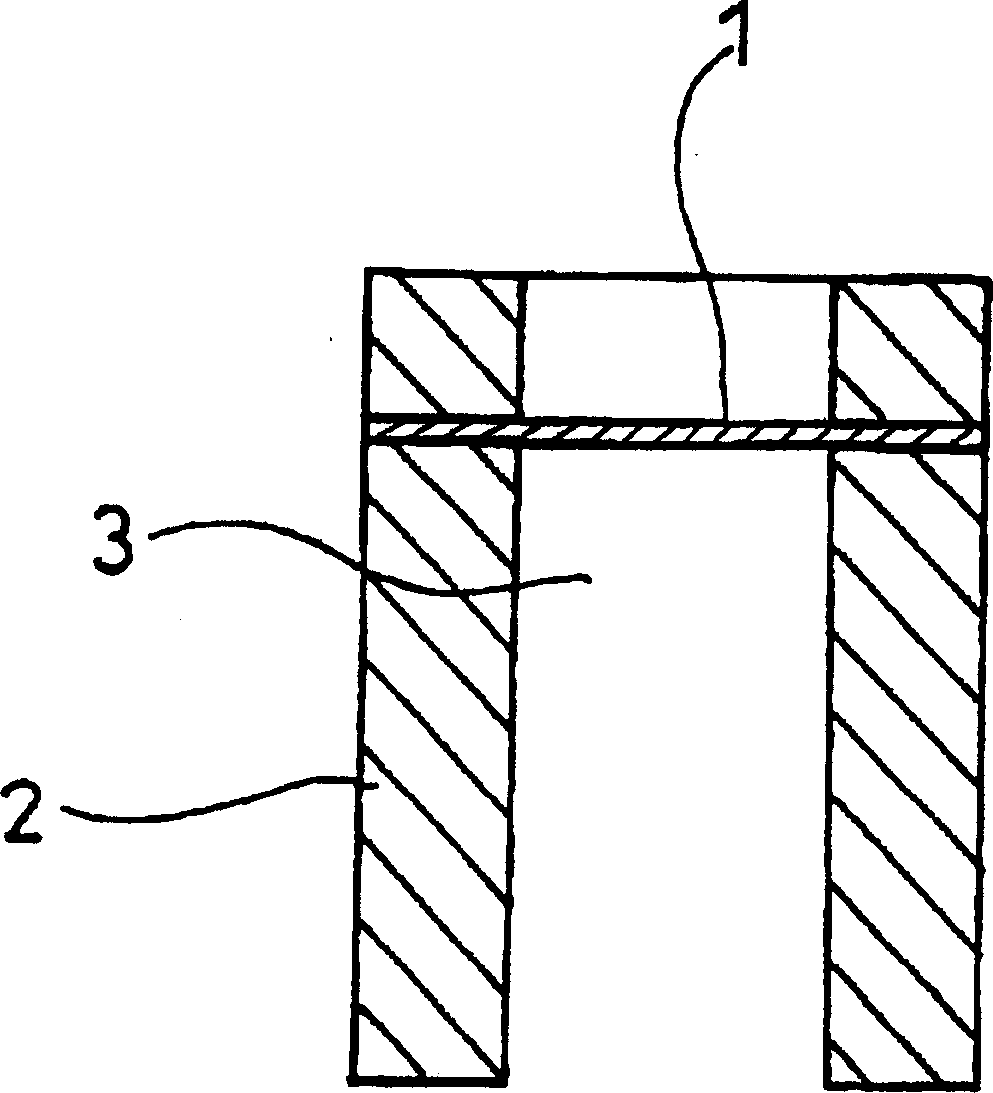
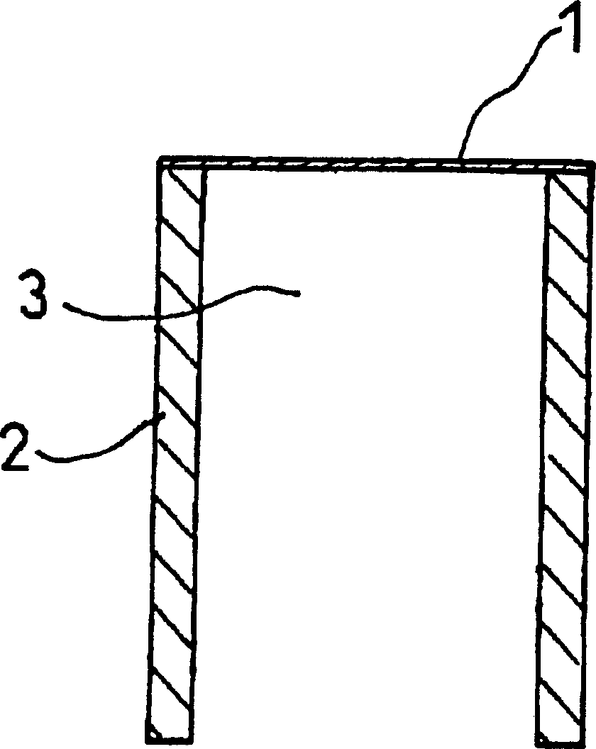
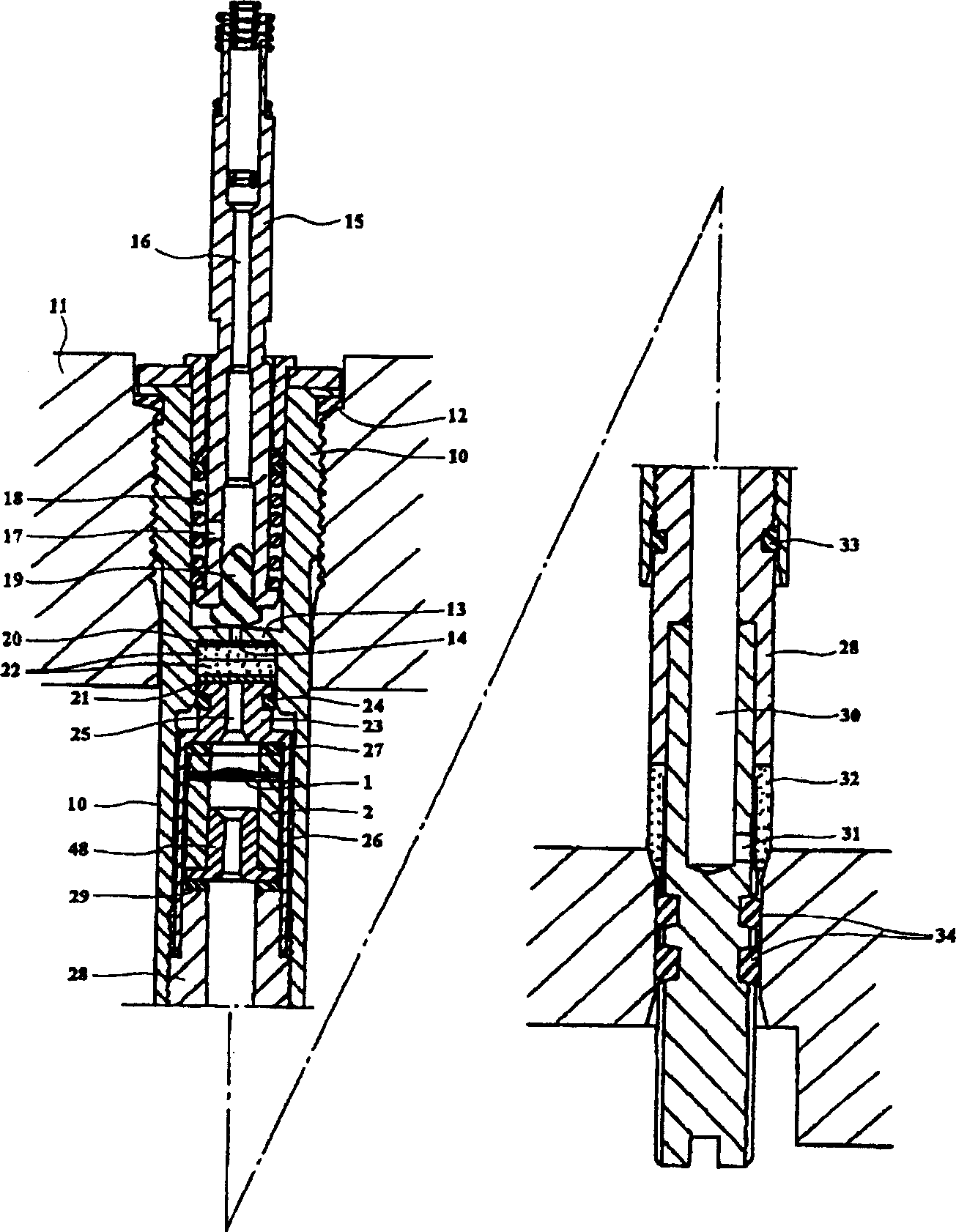
[0023] refer to image 3 , (10) is a fixed cylinder, which is fixedly installed on the upper wall of the storage container (11) with liquid storage gas with O-ring (12) to maintain airtightness. The fixed cylinder (10) constitutes the main component of the flow regulating device, and is composed of a cylinder that penetrates up and down, and is divided into upper and lower chambers by a partition (13) located in the roughly central part. The through hole (14) of perforation on the center communicates with the upper and lower chambers. Utilize the partition wall (13) to insert the combustion nozzle (15) in the upper chamber. At the center of the combustion nozzle (15), a gas ejection passage (16) is arranged axially through and communicated with the upper chamber through the horizontal hole (17). The fuel gas ejected from the upper end of the combustion nozzle (15) is ignited by an ignition spark formed by an appropriate ignition device such as an electric spark, a piezoelect...

Embodiment 2

[0031] Figure 5 Example 2 is shown. Embodiment 2 is that the rotation of the flow regulator of the press-molded flat sheet is performed from above the storage container, which is different from Embodiment 1 in which the flow regulation is performed from the bottom of the container. However, in addition to the difference in such flow regulating devices, other places, especially the two-stage flow regulation consisting of a primary regulation with a diaphragm and a secondary regulation with compression of a molded flat sheet, are characteristic of the invention of the present application. Method and structure are identical with embodiment 1. refer to Figure 5 , the inside of the fixed cylinder (10) fixed on the upper wall of the storage container (11) is divided into upper and lower chambers with a partition (13), and the upper chamber is equipped with a wall adjacent to the partition (13) and clamped in The molded flat sheet (22) between the grooved gasket (21) and the met...


PUM


Abstract

A flow regulating method and apparatus for hydrocarbon gas, characterized in that, hydrocarbon combustion gas is discharged from the liquid state air vessel as a first phase, at first the discharged combustion gas is decompressed by the flow limiting member to limit the upper limit flow in the using range to the max flow, in the limiting max flow range, the compressible flow regulating member from outside can regulate to random flow. The deterioration with time of elastic foaming object is suppressed by combining the minuteness porous membrane with the porous elastic foaming object, thereby obtaining the steady flow regulation persisting for a long time.

Description

technical field [0001] The invention relates to a method and device for regulating the flow of carbonized hydrogen liquefied gas. Background technique [0002] In the past, a gas flow regulating device was known, which is used to store carbonized hydrogen gas in a liquid state in a pressure vessel with a specified volume, and discharge the gas from the container through an on-off valve equipped with a flow regulating mechanism to ignite, for example Used to release gas from smoking lighters, ignition appliances, portable gas cylinders, etc. Smoking lighters and other appliances are equipped with a pressure vessel that stores a small amount of petroleum gas in a liquid state, and a flow regulating member composed of a porous elastic foam such as a molded flat sheet (Moltplain) is compressed from the outside to adjust the vessel. The flow of the fuel gas inside is controlled and discharged through the switch valve, for example, it is sprayed from the burner and forms a flame ...

Claims


Application Information

Patent Timeline
Patent Type & Authority Applications(China)
IPC IPC(8): F23K5/00F23N1/00F23Q2/167G05D7/01
CPCG05D7/0146F23Q2/167G05D7/0186
Inventor 黑岩有
Owner THE JAPAN SMOKING ARTICLES CORP ASSOC
Why Eureka
Try Eureka