Printed circuit board assembly

A technology of printed circuit boards and components, applied in the direction of electrical components, electrical equipment structural parts, card reinforcement boards, etc., can solve the problems of limited quantity, unable to provide sufficient support for PCB, unable to provide separation and calibration, etc., to achieve the promotion ability , the effect of maintaining mechanical alignment and structural rigidity

Inactive Publication Date: 2003-06-11
BITMICRO NETWORKS
View PDF0 Cites 5 Cited by
  • Summary
  • Abstract
  • Description
  • Claims
  • Application Information

AI Technical Summary

Problems solved by technology

Second, traditional designs do not provide adequate support for PCBs subject to high levels of vibration and vibration
Lack of support causes unstable PCB assembly
Third, the lack of adequate support limits the number of PCBs that can be assembled due to their relative instability
Fourth, does not provide precise separation and alignment when the PCB is joined together with the assembled data connector

Method used


Image

  • Printed circuit board assembly
  • Printed circuit board assembly
  • Printed circuit board assembly

Examples


Embodiment Construction

[0015] This invention relates to printed circuit board assemblies. The following description is presented to enable one of ordinary skill in the art to make and use the invention, and is provided in the context of a patent application and its requirements. Various modifications to the preferred embodiments and the general principles and features described herein will be apparent to those skilled in the art. Therefore, the present invention is not intended to be limited to the illustrated embodiments, but is to be accorded the widest scope consistent with the principles and features described hereinafter.

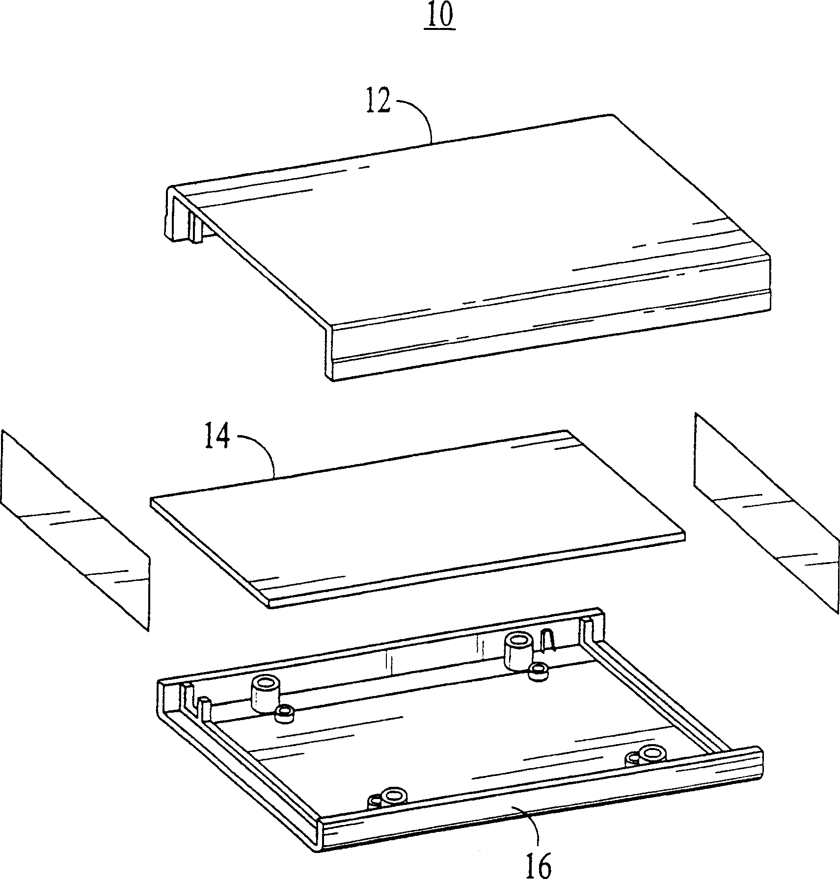
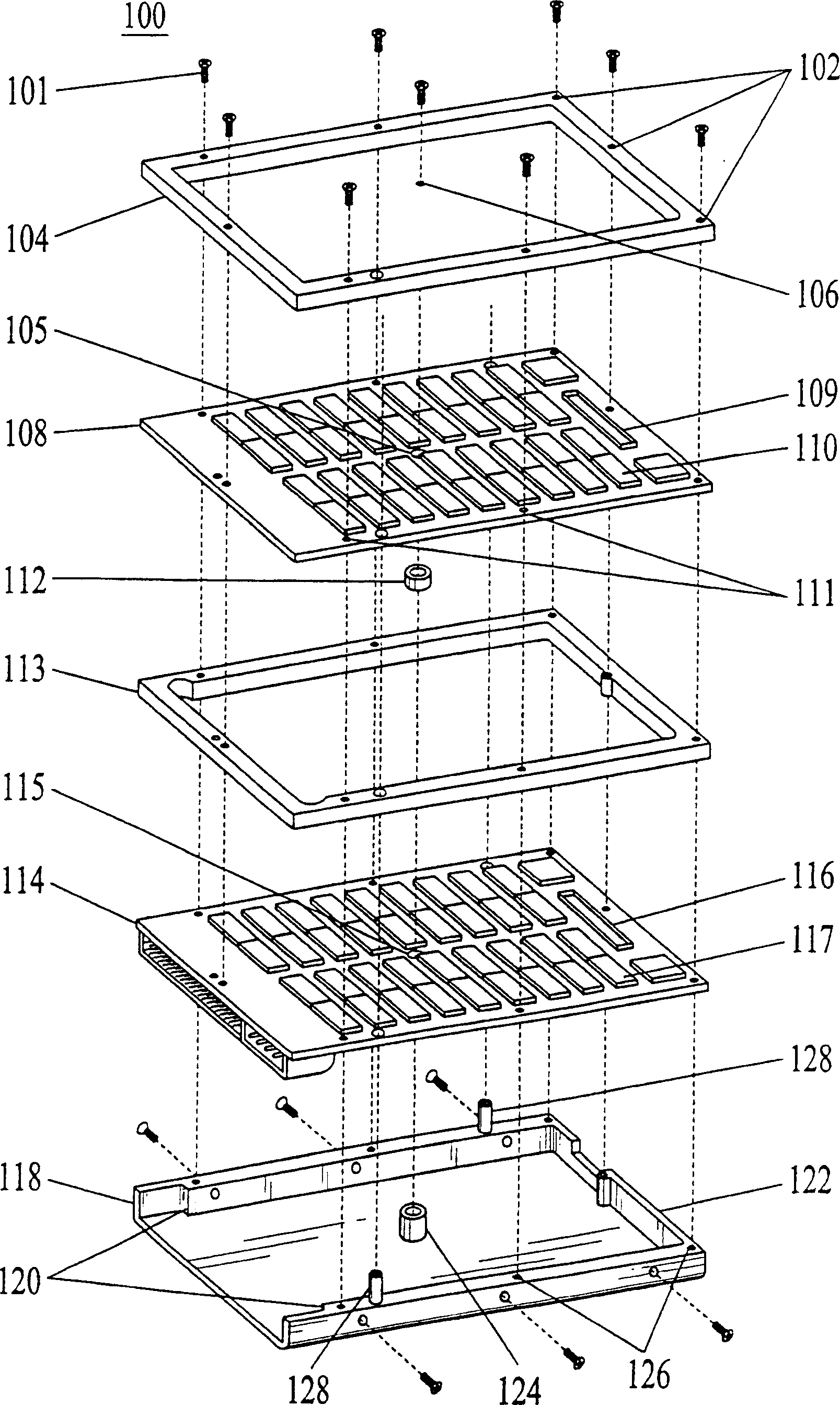
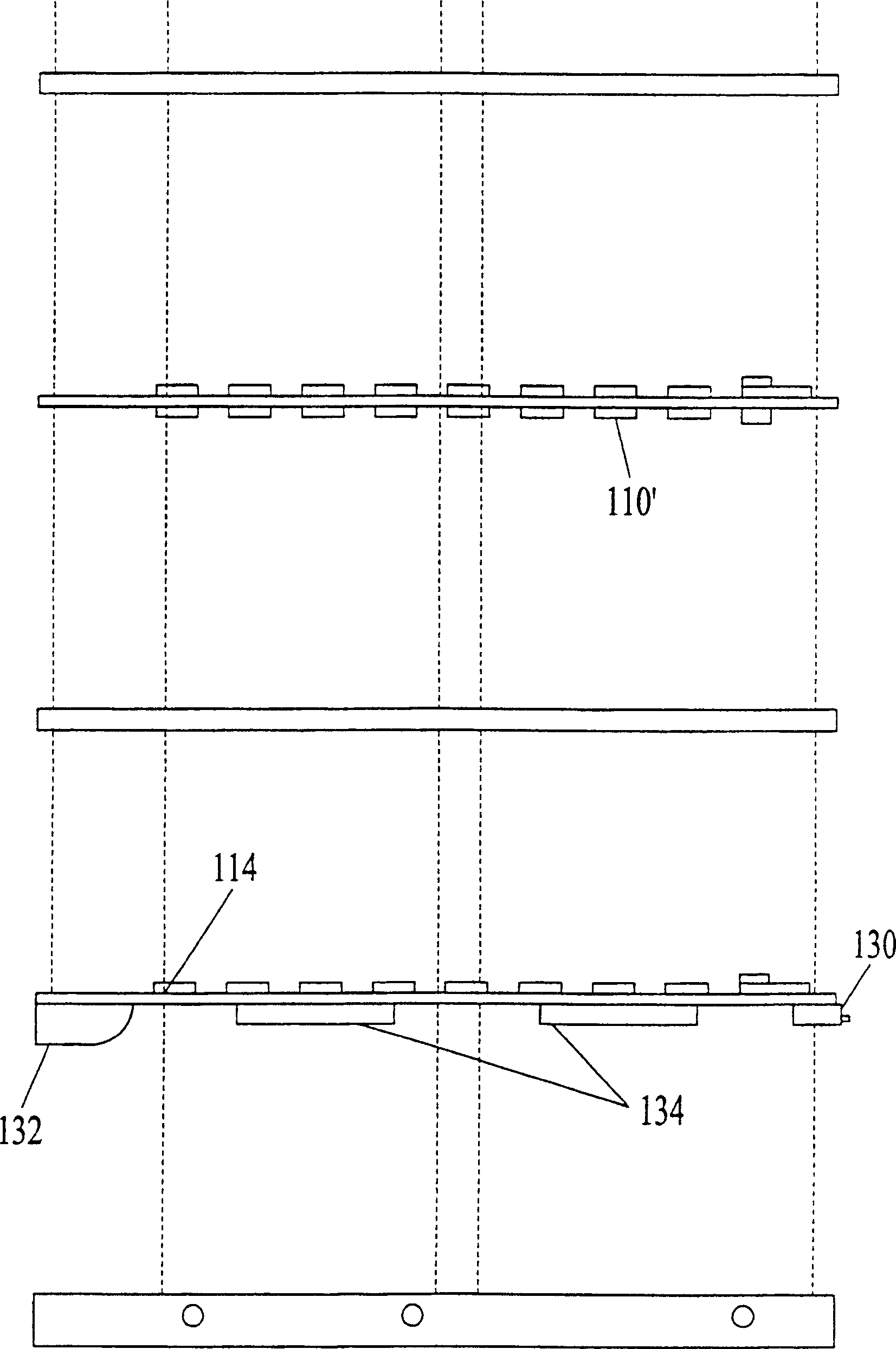
[0016] The device according to the invention is presented in the form of a preferred embodiment. The preferred embodiment of the present invention is an improved printed circuit board assembly. The printed circuit board assembly according to the invention incorporates a printed circuit board extending over the entire base area. By extending the printed circuit boards acro...


PUM


Abstract

A printed circuit board assembly (100) wherein the assembly comprises a first plate (104), a second plate (118) attachably coupled to the first plate (104), and at least one printed circuit board (108, 114) sandwiched between the first plate (104) and the second plate (118), the at least one circuit board (108, 114) extending over the entire area of the first and second plates (104, 118). Utilizing an assembly in accordance with the present invention maximizes the available space on each of the circuit boards. By maximizing the available space, more electronic circuitry can be incorporated onto the board. Furthermore, the exterior spacer design (113) together with interior spacer elements (112, 124) firmly secures each circuit board while maintaining a constant separation between each board. This facilitates the ability to stack more circuit boards, while maintaining the mechanical alignment and structural rigidity necessary for the stacking data connectors (109, 116) to function properly should the assembly be subjected to a sudden shock or vibration.

Description

[0001] Cross references to related applications [0002] This application is related to a pending application with serial number JAS 1458P entitled "Removable Visual Indicating Structures for Printed Circuit Boards", filed on the same day as this application and appointing the same agent. field of invention [0003] This invention relates generally to computer components and in particular to improved techniques for assembling and assembling printed circuit boards. Background of the invention [0004] Computer systems continually demand more power, more storage, and faster operation, and in many cases, they require it in smaller physical components. Accordingly, in order to meet these demands, the packing density of printed circuit boards (PCBs) of those computer systems has increased. Additionally, there are many standard industry specifications that place additional space constraints in the size of the PCB as well as greatly increased tolerance for vibration and vibration....

Claims


Application Information

Patent Timeline
IPC IPC(8): H05K7/14
CPCH05K7/142H05K7/1461
Inventor 罗兰·F·波特曼埃德加·雅韦·格雷戈里奥斯
Owner BITMICRO NETWORKS
Why Eureka
Try Eureka