Injection Blow Molding Device for the Manufacture of a Thin-Walled Part and Process

a technology of injection molding and thin-walled parts, which is applied in the direction of manufacturing tools, applications, drawing profiling tools, etc., can solve the problems of exceeding the technical capabilities of materials used, difficult to manufacture thin-walled parts by injection molding, and high pressur

a technology of injection molding and thin-walled parts, which is applied in the direction of manufacturing tools, applications, drawing profiling tools, etc., can solve the problems of exceeding the technical capabilities of materials used, difficult to manufacture thin-walled parts by injection molding, and high pressur

US20090220809A1Active Publication Date: 2009-09-03DES EAUX MINERALES DEVIAN

Image

  • Injection Blow Molding Device for the Manufacture of a Thin-Walled Part and Process
  • Injection Blow Molding Device for the Manufacture of a Thin-Walled Part and Process
  • Injection Blow Molding Device for the Manufacture of a Thin-Walled Part and Process

Examples


example 1

Conventional PET Preform (Weight 17 g; Length 90.44 mm) and Process for Obtaining it
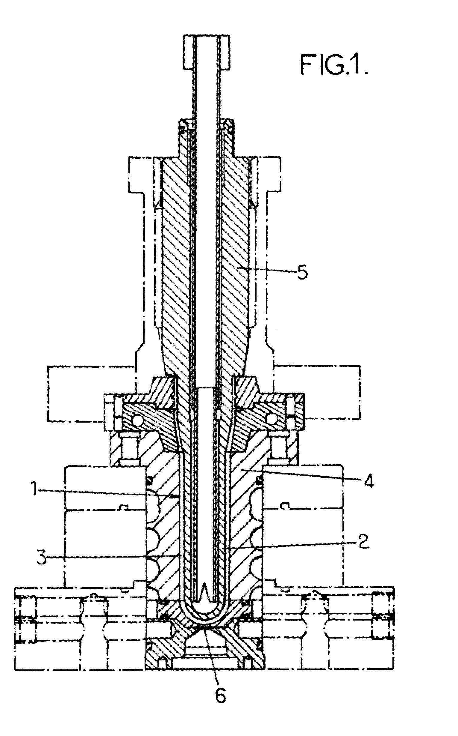
Device Employed

[0093]The preforms are produced on injection molding machines equipped with a multicavity mold.

[0094]The PET material, predried so as to prevent hydrolysis as it undergoes melting, is transferred under gravity to the plasticization screw where it progressively passes from the solid state to the molten state. This plasticization must be carried out according to the rules of the art so as to achieve good homogeneity of the melt. The molten material is transferred forward of the screw by rotation of the screw, increase in the temperature and increase in pressure: extrusion.

[0095]There is a build-up of molten material forward of the screw, this material being transferred into the injection pot by the valve passing into the transfer position, and an amount of material corresponding to one complete mold (preform weight, in this case 17 g, multiplied by the number of cavities) is transferred....

example 2

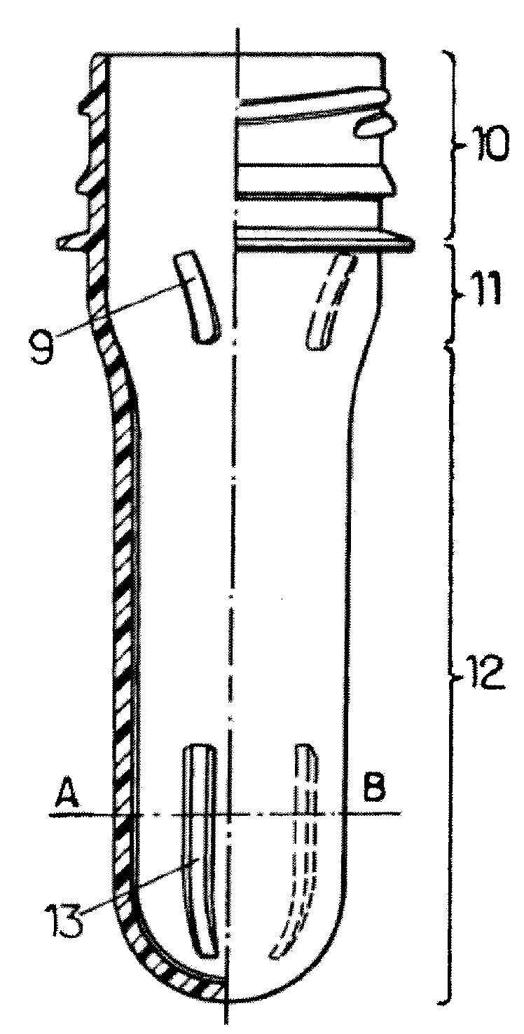
Preform According to the Invention (FIG. 3)

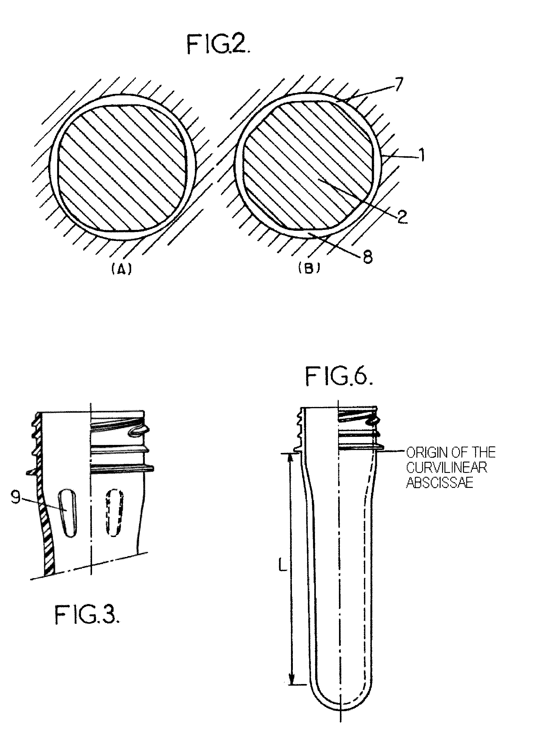
[0111]The lightening of containers requires designing preforms of ever thinner wall thickness, the thickness / length ratio of which becomes less than 2. In this case, the design of the preform will include PFCs for allowing the cavity to be filled. The manufacturing process is the same as that presented above.

[0112]The lightening of the preform is achieved by changing the core (limited investment cost), thereby reducing the thickness of the preform.

[0113]Thus, for a preform of the same length as that of example 1, namely 90.44 mm, it will be possible to produce a lightened preform weighing 15.35 g. The average thickness of this preform will be 1.8 mm and this can be filled only in the presence of the PFCs in the mold.

[0114]The addition of the PFCs allows the injection pressure to be brought back down to between 100 and 130 bar, compared with a maximum pressure of 150 bar, which maximum pressure, without the addition of PFCs, nevertheless doe...


PUM

PropertyMeasurementUnit
lengthaaaaaaaaaa
thicknessaaaaaaaaaa
circumferenceaaaaaaaaaa

Abstract

The invention concerns an injecting / blowing device comprising at least one mold for injecting a thin-walled hollow preform capable of being transformed into a more voluminous hollow body by blowing, said mold including a counter mold defining the inner surface of the cavity, a cure located in the cavity and spaced apart from said inner surface, a preform impression located between the counter mold inner surface and the core, and which will receive the melt, at least two main preferential flow channels (CEPP) optionally at least two secondary preferential flow channels (CEP), each CEP being delimited by at least one recessed zone at the surface of the core and the inner surface of the cavity. Said device is characterized in that: the main CEP are located only at the impression zone corresponding to the zone for transforming the preform; and in that the optional secondary CEP are discontinuous, distinct from the main CEP, and located at the impression zone corresponding to the base and / or the body and / or the ring of the preform.

Description

TECHNICAL FIELD OF THE PRESENT INVENTION[0001]The subject of the present invention is the injection molding of thin-walled parts, especially preforms.[0002]The invention blow molding or ISBM (Injection Stretch Blow Molding) technique is well known and used for producing parts from thermoplastics. These parts may take the form of food containers, such as bottles.[0003]The invention blow molding technique firstly comprises injection molding consisting of the following steps: drying of the material used if necessary before it melts; plasticization; injection of the material into the mold comprising a core and a countermold forming a molding cavity which corresponds to the molding impression; cooling; demolding; and removal of the preforms, and then blow molding comprising the following steps: reheating of the preforms; stretch-preblowing and blowing.[0004]The injection molding aspect is more specially of interest within the context of the invention.PRIOR ART[0005]It is known that it is...

Claims


Application Information

Patent Timeline
03 Sep 2009
Publication
US20090220809A1
IPC
B29B11/08; B29C45/27; B28B7/28; B29C45/40
CPC
B29B11/08; Y10T428/1352; B29B2911/1402; B29B2911/14026; B29B2911/14033; B29B2911/1404; B29B2911/14086; B29B2911/14093
Inventors
BERTHEOL, GILLES; COLLOUD, ALAIN