Automatic prestressing extension devices

A tensioning device and prestressing technology, applied in the direction of control without feedback, construction, building structure, etc., can solve the problems of difficult to accurately control the tensioning force, large control error of pressurization operation, etc., to ensure the design intent, improve the Safety, fast construction effect

Inactive Publication Date: 2003-06-18
李珠
View PDF1 Cites 35 Cited by
  • Summary
  • Abstract
  • Description
  • Claims
  • Application Information

AI Technical Summary

Problems solved by technology

[0004] The present invention solves the problem of large pressure operation control error caused by the open-loop control of the existing prestressed tensioning device, and it is di

Method used


Image

  • Automatic prestressing extension devices
  • Automatic prestressing extension devices
  • Automatic prestressing extension devices

Examples


Embodiment Construction

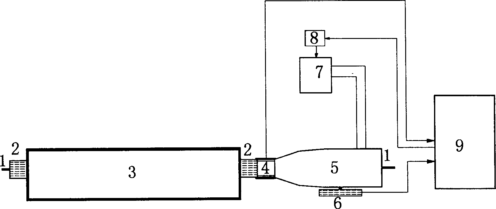
[0013] Fully automatic prestressed tensioning device, including the tensioning jack 5 driven by the oil pump 7, the force sensor 4, the displacement sensor 6 and the control assembly 9 of the tensioning device. Solenoid valve 8 controlled by the assembly.

[0014] The displacement sensor 6 is fixed below the jack 5, and its electrical signal output end is connected with the signal input end of the control assembly with a wire; the electrical signal output end of the force sensor 4 is also connected with the signal input end of the control assembly through a wire.

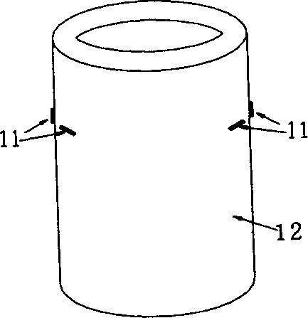
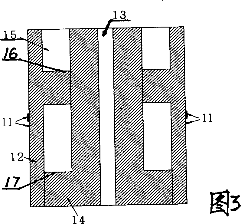
[0015] A force sensor having the following structure can be used. The force sensor 4 is composed of a force-sensing elastic member 12 with a strain gauge 11 fixed on its outer surface, and a plug 14 located in the force-sensing elastic member on which a prestressed tendon hole 13 is formed. There are eight strain gauges fixed on the force sensor, and the eight strain gauges are bridge-connected. The inner side of ...


PUM


Abstract

A full-automatic prestress stretching machine is composed of a control assemblage consisting of jack driven by oil pump, force sensor, displacement sensor and stretching unit, and electromagnetic valve in the oil channel of oil pump and controlled by said control assemblage. Its advantages are high stretching precision (1%), and high automation and digitalization level.

Description

technical field [0001] The invention relates to a device for performing prestress treatment on prestress components in civil engineering, in particular to a fully automatic prestress stretching device. Background technique [0002] At present, in the field of civil engineering, the most traditional prestressed tensioning system used for tensioning prestressed members is to pull the jack driven by the oil pump. The tension is controlled by the reading of the pressure gauge of the oil pump, and the tension of the prestressed tendons is controlled by manual measurement. The elongation value has the following defects: 1) the calibration error of tension and pressure gauge and the reading error of pressure gauge are relatively large; 2) the reading of pressure gauge is unstable, it is difficult to read accurately, and the reading speed is slow, which can only be known by converting the reading of pressure gauge The size of the tension force does not form an intuitive concept of t...

Claims


Application Information

Patent Timeline
IPC IPC(8): E04G21/12G05D3/10
Inventor 李珠郭全全王显耀贾敏智
Owner 李珠
Why Eureka
Try Eureka