Hydraulic tensioner

A hydraulic tensioner, tension technology, applied in transmission, belt/chain/gear, mechanical equipment, etc., can solve problems such as vibration, large gap between claw-shaped elements and lateral holes, etc.

Inactive Publication Date: 2003-07-02
BORG WARNER MORSE TEC JAPAN KK
View PDF2 Cites 16 Cited by
  • Summary
  • Abstract
  • Description
  • Claims
  • Application Information

AI Technical Summary

Problems solved by technology

However, due to the excessive clearance between the claw element and the transverse hole, increasing the stroke may cause vibrations

Method used


Image

  • Hydraulic tensioner
  • Hydraulic tensioner
  • Hydraulic tensioner

Examples


Embodiment Construction

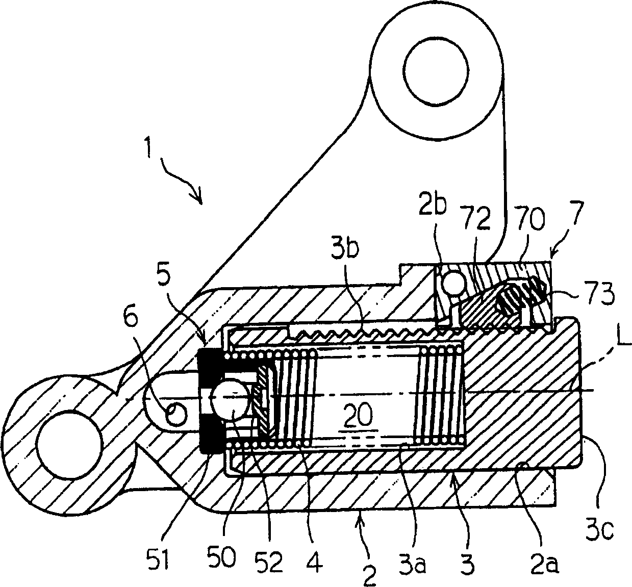
[0020] Such as figure 1 As shown, the hydraulic tensioner 1 includes a housing 2, a hollow plunger 3 slidably installed in a hole 2a of the housing 2, and a spring 4 as a first pressing element, which moves along the hollow plunger 3 The plunger is pushed in the direction protruding from the hole 2a.

[0021] In the housing 2 , a fluid chamber 20 is formed by an internal space 3 a between the inner wall surface of the hole 2 a and the interior of the plunger 3 . A one-way valve 5 is provided at the bottom of the inner hole 2a of the housing to allow the fluid to flow into the cavity 20, but prevent the fluid from flowing in the opposite direction. The one-way valve 5 includes a ball 50 , a ball seat 51 in contact with the ball 50 , and a pressing spring 52 pushing the ball 50 toward the ball seat 51 . The formation of the one-way valve can also adopt any other suitable structure. The housing 2 also has a fluid channel 6 for communicating the cavity 20 with an external sourc...


PUM


Abstract

A hydraulic tensioner is provided to reduce the number of parts, to secure the backlash, and to prevent the plunger from moving backward. A hydraulic tensioner comprising a hollow plunger having rack teeth formed on a portion of an outer circumferential surface, slidably received in a bore of the housing, where the plunger has an inner space to form a fluid chamber with the bore. A slider housing portion, having an inclined surface, located in the housing, receives a wedge-shaped slider having a ratchet portion adapted to engage with the rack teeth of the plunger and a second side surface. The wedge-shaped slider being slidable along the inclined surface of the slider housing portion in a direction crossing an axial centerline of the plunger. The hydraulic tensioner further includes a first spring biasing the plunger in a protruding direction, and a second spring biasing the slider such that the slider moves along the inclined slide surface of the slider housing portion. A ''wedge-effect'' prevents the plunger from moving backwards.

Description

【Technical field】 [0001] The present invention relates to the field of tensioners for providing tension to chains, belts or the like. More specifically, the present invention relates to a tensioner with a pawl mechanism having a slider to prevent retraction of the plunger after hydraulic pressure is lowered. 【Background technique】 [0002] A hydraulic tensioner usually consists of a housing, a hollow plunger, which is mounted in a hole in the housing, where the plunger is pushed by a spring in the direction of its extension, and includes a fluid volume defined by the hole in the housing and the plunger. cavity. In operation, the chain or belt exerts a force on the distal end of the plunger that is balanced by the force of the spring and the hydraulic pressure in the fluid chamber. [0003] During engine start-up, when the chain exerts a force on the distal end of the plunger, the hydraulic pressure in the chamber is not sufficient at that time, and as a result, the plunger...

Claims


Application Information

Patent Timeline
Patent Type & Authority Applications(China)
IPC IPC(8): F16H7/08
CPCF16H7/0848F16H2007/0806F16H2007/0812F16H2007/0853F16H2007/0859F16H7/08
Inventor S·索恩皮沃
Owner BORG WARNER MORSE TEC JAPAN KK
Why Eureka
Try Eureka