Radio communication system, base station, trunking station, mobile station and group transmitting control method

A technology for a wireless communication system and a relay station, which is applied in the field of wireless communication systems and can solve the problems of increased communication volume, great influence on the service area, and decreased system processing capacity.

Inactive Publication Date: 2003-07-16
NTT DOCOMO INC
View PDF0 Cites 15 Cited by
  • Summary
  • Abstract
  • Description
  • Claims
  • Application Information

AI Technical Summary

Problems solved by technology

[0007] However, in the CSMA-based multi-hop method previously proposed, there is a problem of terminal concealment (since adjacent stations transmit signals at the same frequency, a station located in a heavy area of ​​the wireless area of ​​these adjacent stations is due to two The collision of two received radio waves makes it impossible to receive signals (for example, refer to the paper published in "IEEE communication magazine (2001)" (title: "Does IEEE 802.11 MAC protocol work well on multihop wireless ad-hoc networks", author: Shugong Xu, et al. .Al)), the problem of increased traffic and reduced processing capacity of the system caused by the terminal concealment problem has not yet been resolved
[0008] As explained above, in the conventional cellular mobile communication system, the layout of the base station greatly affects the range of the service area, and there is a problem that the mobile station cannot establish communication in an area where the received signal level of the radio wave of the base station is low.
In addition, although the multi-hop method using CSMA and TDMA in the past is promising as a device that can enable the above-mentioned mobile stations that cannot communicate, the arrangement of the relay station will cause problems such as terminal concealment, resulting in increased traffic and The processing power of the system is reduced

Method used


Image

  • Radio communication system, base station, trunking station, mobile station and group transmitting control method
  • Radio communication system, base station, trunking station, mobile station and group transmitting control method
  • Radio communication system, base station, trunking station, mobile station and group transmitting control method

Examples


Embodiment Construction

[0103] Next, an embodiment of the present invention will be described with reference to the drawings.

[0104] (Overall contents of the mobile communication system)

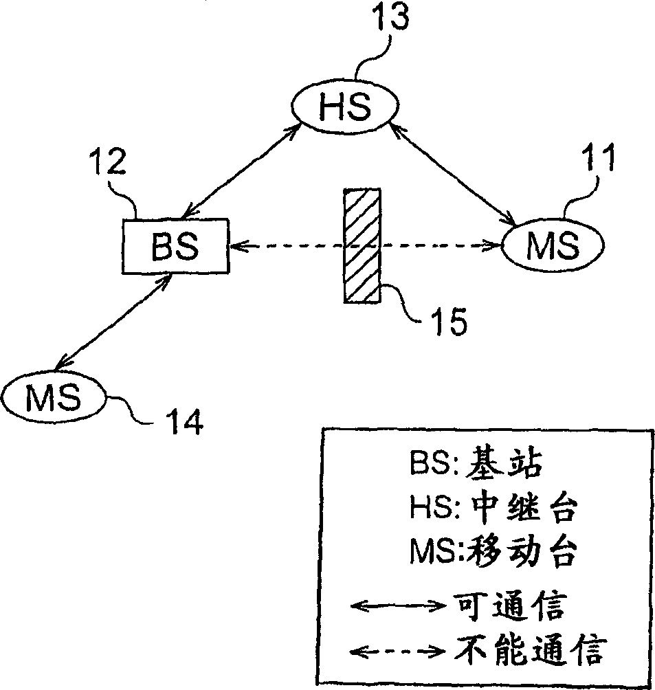
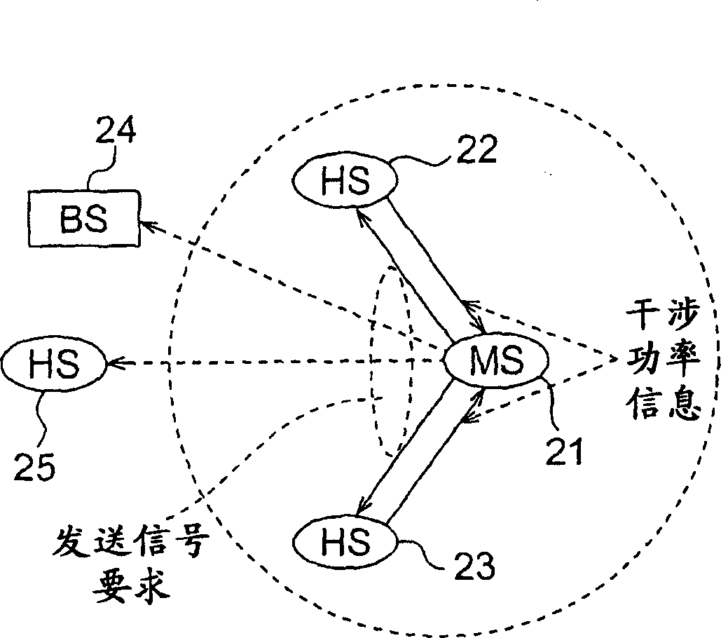
[0105] In the mobile communication system of the present embodiment, as the stations related to one communication, there are three "base stations", "relay stations", and "mobile stations". The base station is a station that can be connected to other base stations through the core network, and the mobile station is a terminal that initially requests packet transmission or finally receives a packet. In addition, a relay station is a terminal (relay terminal) that plays a role of relaying a packet from a mobile station to a base station or relaying a packet from a base station to a mobile station, and consumes power by relaying packets, Therefore, in addition to terminals operated by batteries in the past, terminals that receive power supply from solar cells, generators, or lines can also be considered. In order to...


PUM


Abstract

The object is to control interference in a permissible range by applying the CDMA system to signal collision in the conventional CSMA and TDMA base multihop systems and to relax the hidden terminal problem and others to enhance the throughput of the entire system by grouping of channel groups in multihop transmission and by control of transmission based on an interference level from another station. A multihop relay station calculates a desired signal level, for example, from an interference level at its own station of a packet sent from a mobile station, and notifies the mobile station of the desired signal level; and the mobile station calculates a transmission power amount of a packet from the desired signal level, determines whether the packet is transmissible to the station as a source of the desired signal level, on the basis of the transmission power amount, and transmits the packet by a power of the transmission power amount to the source station determined as a packet-transmissible station. On this occasion, an interference signal is weakened by assignment of channel groups 1, 2 for transmission of signals.

Description

technical field [0001] The present invention relates to a wireless communication system, a base station, a relay station, a mobile station, and a packet transmission control method utilizing a multi-hop technology. Connection to the base station. [0002] In the wireless communication system of the present invention, three stations, "base station", "relay station", and "mobile station", can be cited as stations related to one communication, but in the following description, "base station" means The core network is connected to other base stations. "Mobile station" refers to the terminal that initially requests packet transmission or finally receives the packet (that is, becomes the destination of the packet), and "relay station" refers to the terminal that relays the packet from the mobile station. A terminal that relays packets to or from a base station to a mobile station. [0003] In addition, "packet transmission direction" is a general term for the "uplink direction" fr...

Claims


Application Information

Patent Timeline
Patent Type & Authority Applications(China)
IPC IPC(8): H04B7/005H04B7/155H04L12/28H04L12/56H04W24/00H04W28/04H04W28/18H04W48/08H04W52/24H04W52/28H04W52/46H04W88/04H04W92/10
CPCH04W68/00H04W52/247H04W52/46H04W48/08H04W28/18H04W88/04H04W24/10H04W92/10H04W28/04H04W52/286
Inventor 竹田真二藤原淳吉野仁大津徹山尾泰
Owner NTT DOCOMO INC
Why Eureka
Try Eureka