Quieter used in cleaner
A sound-absorbing device and vacuum cleaner technology, applied in vacuum cleaners, applications, household appliances, etc., can solve problems such as high noise, achieve noise reduction, good noise reduction effect, and reduce working noise
- Summary
- Abstract
- Description
- Claims
- Application Information
AI Technical Summary
Problems solved by technology
Method used
Image
Examples
Embodiment 1
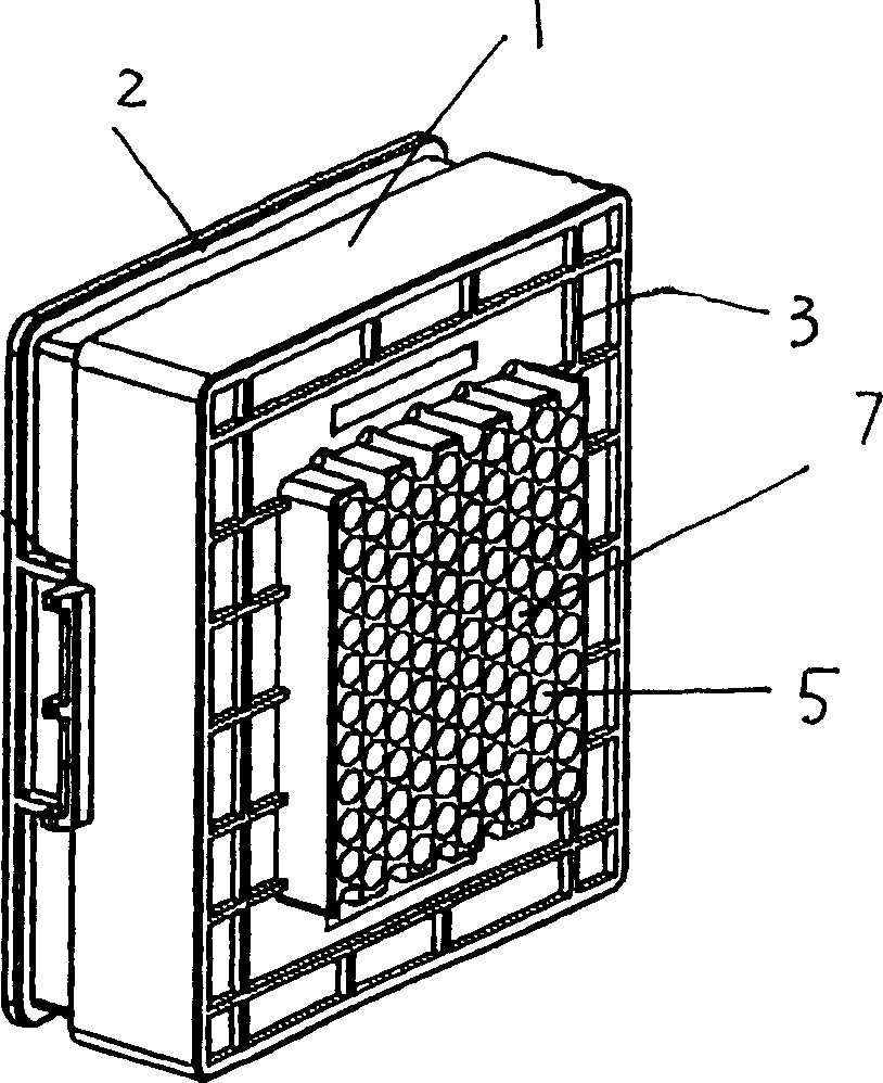
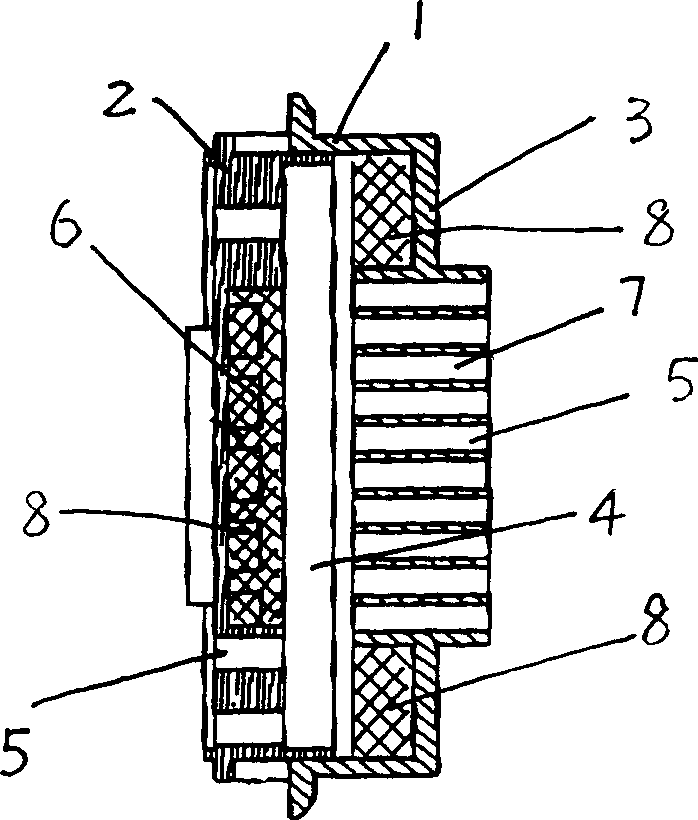
[0019] Embodiment one: if figure 1 , figure 2 As shown, a noise reduction device for a vacuum cleaner includes a closed casing (1), the casing (1) is provided with an air inlet end (2) and an air outlet end (3), the air inlet end (2) and the air outlet end (3). The air outlets (3) are respectively located at the front and rear ends of the casing (1), the air inlet direction is the same as the air outlet direction, and a muffler cavity (4) is provided between the air inlet end (2) and the air outlet end (3) , the air inlet end (2) and the air outlet end (3) are provided with an air inlet area (6) and an air outlet area (7) composed of densely distributed pipe-like exhaust holes (5), and the air inlet cross-sectional area and the air outlet cross-sectional area are respectively less than the cross-sectional area of the muffler cavity (4); the air inlet area (6) on the air inlet end (2) is located around the air inlet end (2), and the inner wall of the air inlet end (2) The ...
Embodiment 2
[0020] Embodiment two: if figure 2 As shown, a noise reduction device for a vacuum cleaner includes a closed casing (1), the casing (1) is provided with an air inlet end (2) and an air outlet end (3), the air inlet end (2) and the air outlet end (3). The air outlets (3) are respectively located at the front end and the side end of the housing (1), the air inlet direction and the air outlet direction have an included angle, and a muffler chamber ( 4), the air inlet end (2) and the air outlet end (3) are provided with an air inlet area (6) and an air outlet area (7) composed of densely distributed pipe-like exhaust holes (5), and the air inlet The cross-sectional area and the wind outlet cross-sectional area are respectively smaller than the cross-sectional area of the muffler chamber (4).
Embodiment 3
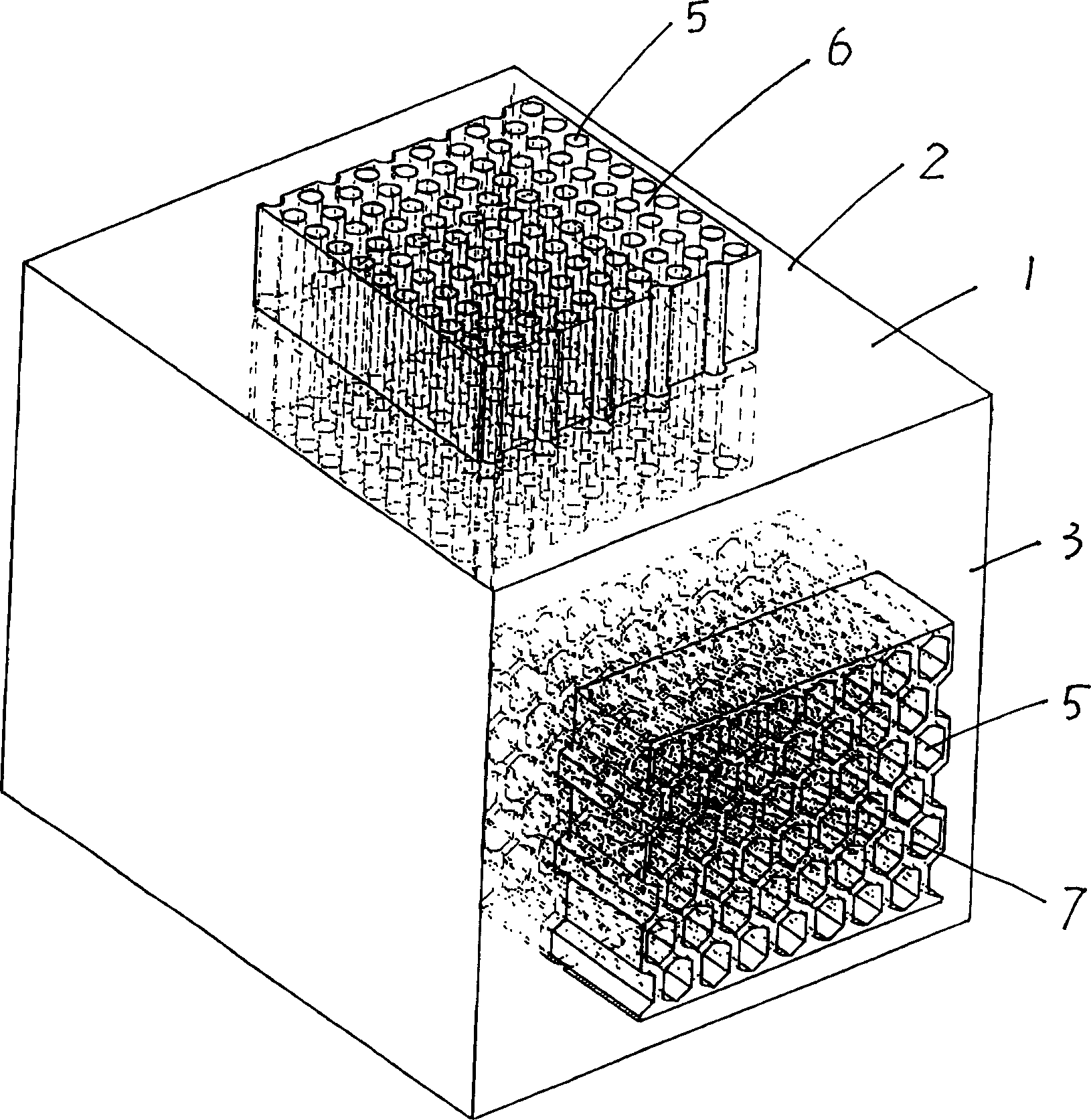
[0021] Embodiment three: as Figure 4 As shown, a noise reduction device for a vacuum cleaner includes a closed casing (1), the casing (1) is provided with an air inlet end (2) and an air outlet end (3), the air inlet end (2) and the air outlet end (3). The air outlets (3) are respectively located on different sides of the casing (1), the air inlet direction and the air outlet direction have an included angle, and a muffler chamber (4) is provided between the air inlet end (2) and the air outlet end (3) , the air inlet end (2) and the air outlet end (3) are provided with an air inlet area (6) and an air outlet area (7) composed of densely distributed pipe-like exhaust holes (5), and the air inlet cross-sectional area and the cross-sectional area of the air outlet are respectively smaller than the cross-sectional area of the muffler cavity (4).
[0022] Since the air inlet area (6) and the air outlet area (7) of the present invention are composed of densely distributed pip...
PUM
 Abstract
Description
Claims
Application Information
 - R&D
- Intellectual Property
- Life Sciences
- Materials
- Tech Scout
- Unparalleled Data Quality
- Higher Quality Content
- 60% Fewer Hallucinations
Browse by: Latest US Patents, China's latest patents, Technical Efficacy Thesaurus, Application Domain, Technology Topic, Popular Technical Reports.
© 2025 PatSnap. All rights reserved.Legal|Privacy policy|Modern Slavery Act Transparency Statement|Sitemap|About US| Contact US: help@patsnap.com


