
Method for removing image grating on pixel type projected display

A display and grid technology, which is applied in the image grid removal and system field of pixel projection display, can solve the problems affecting the appearance of the image, etc., and achieve the effect of simple system, small influence of light energy, and high optical efficiency

Inactive Publication Date: 2003-07-23
ZHEJIANG UNIV
View PDF0 Cites 2 Cited by
  • Summary
  • Abstract
  • Description
  • Claims
  • Application Information

AI Technical Summary

Problems solved by technology

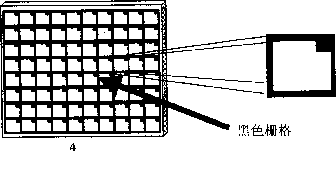
However, pixel-based projection displays have a common disadvantage. Since the image screen is composed of pixels, and there is a certain interval between each pixel, black grids will be formed in the displayed screen. The black grid seriously affects the aesthetics of the image
This is the biggest difference and disadvantage between digital projection display technology and analog traditional film projection display.

Method used


Image

  • Method for removing image grating on pixel type projected display
  • Method for removing image grating on pixel type projected display
  • Method for removing image grating on pixel type projected display

Examples


Embodiment Construction

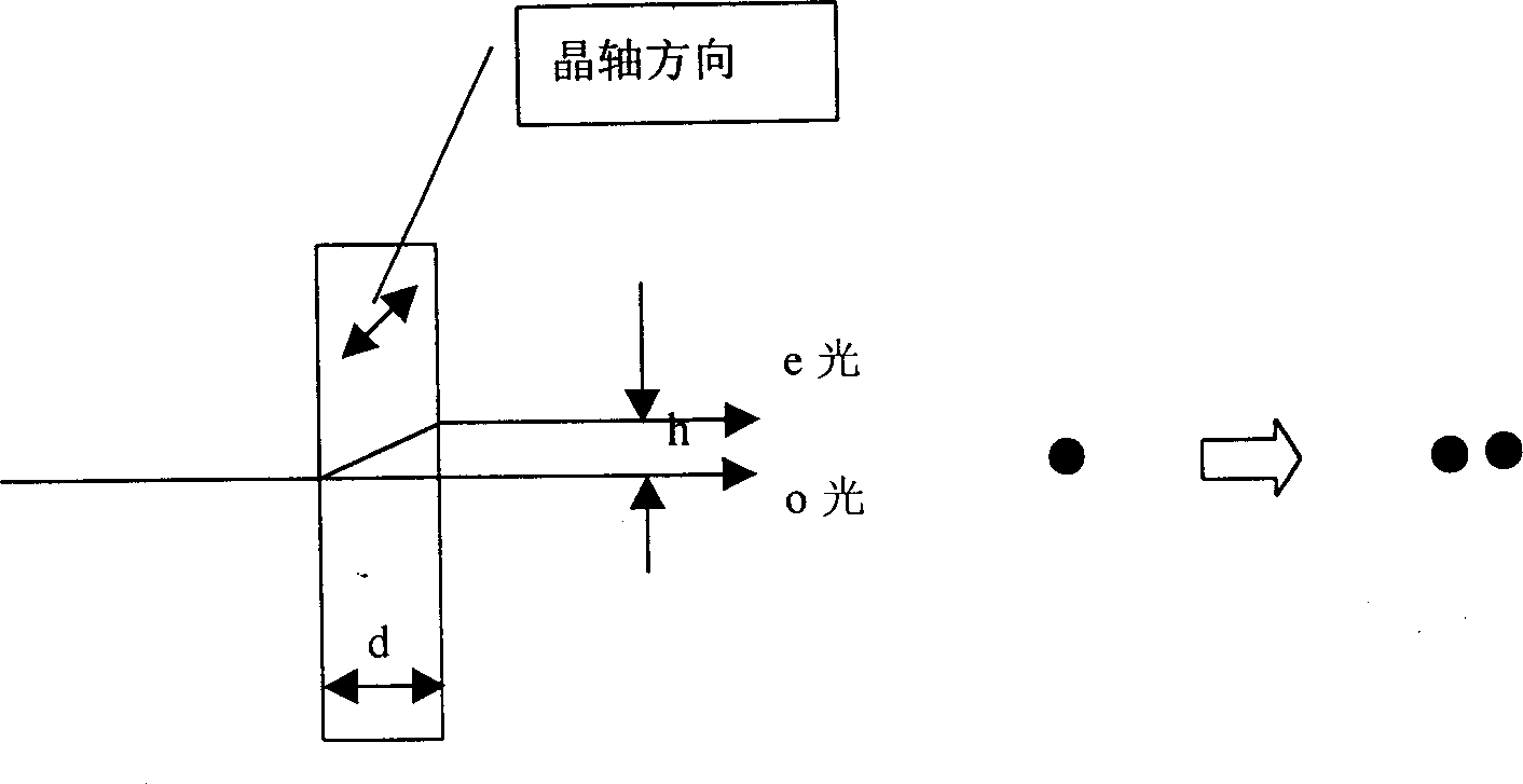
[0016] An image grid removal method for a pixel-based projection display is a method for implementing inter-pixel grid removal by superimposing multiple images with small-scale displacements.

[0017] The said multi-image optical crystal wave plate is a monolithic black grid removal method of misalignment and stacking in one direction. The multi-image optical crystal wave plate adopts the superposition of multiple optical crystals to form the black grid removal method of multi-directional misalignment and superposition in the image space. An optical crystal wave plate or a combination of multiple optically anisotropic sheets that produce multiple images is placed in front of the pixel spatial light modulator, or placed in the light path before entering the projection objective lens.

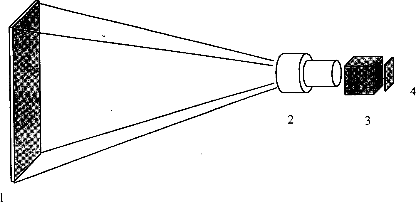
[0018] The image grid removal system of a pixel-based projection display has a screen 1, an objective lens 2, a color separation, light combining or polarizing prism system 3, a spatial light mod...


PUM


Abstract

Superposing the multiple images with displacements in microscales realizes to remove the grids between the pixels. The system includes the screen, the object lens, the color separation, the light mergence or polarizing prism system, the spatial light modulator and the image smooth, which is located in front of the modulator or in the light path before entering the project lens. Gate function convolution lowpass filtering theory is applied. The bipartite component is utilized to remove the black grids in the display of the spatial light modulator of the matrix pixels. The bipartite component can be made from the material with anistropy. The invention technique can be utilized in Liquid Crystal Display, Liquid Crystal on Silicon, Digital Light Processor as well as other array spatial light modulator.

Description

technical field [0001] The invention relates to an image grid removal method and system for a pixel type projection display. Background technique [0002] In modern projection display technology, pixel projection display has become the mainstream technology. Such as liquid crystal projection display technology based on thin film transistor liquid crystal display (TFT-LCD), LCOS projection display technology of liquid crystal display on silicon substrate, and digital light processing projection display technology DLP based on digital micromirror DMD. These large-screen projection technologies are widely used in office, advertising, audio-visual teaching and home entertainment. However, pixel-based projection displays have a common disadvantage. Since the image screen is composed of pixels, and there is a certain interval between each pixel, black grids will be formed in the displayed screen. The black grid seriously affects the aesthetics of the ima...

Claims


Application Information

Patent Timeline
IPC IPC(8): G02B27/10G02B27/18G02B27/28G02F1/01
Inventor 刘旭刘向东李海峰
Owner ZHEJIANG UNIV
Learn More