Liquid crystal display

A technology of a liquid crystal display device and a liquid crystal display panel, which is applied in identification devices, light guides, optics, etc., can solve problems such as effective display area limitations, and achieve the effect of avoiding brightness reduction

Inactive Publication Date: 2003-07-23
JAPAN DISPLAY INC
View PDF3 Cites 20 Cited by
  • Summary
  • Abstract
  • Description
  • Claims
  • Application Information

AI Technical Summary

Problems solved by technology

Therefore, the effective display area of ​​the liquid crystal

Method used


Image

  • Liquid crystal display
  • Liquid crystal display
  • Liquid crystal display

Examples


Embodiment Construction

[0036] Embodiments of the present invention will be described in detail below with reference to the drawings of the embodiments. The same code|symbol is attached|subjected to the same part in each figure.

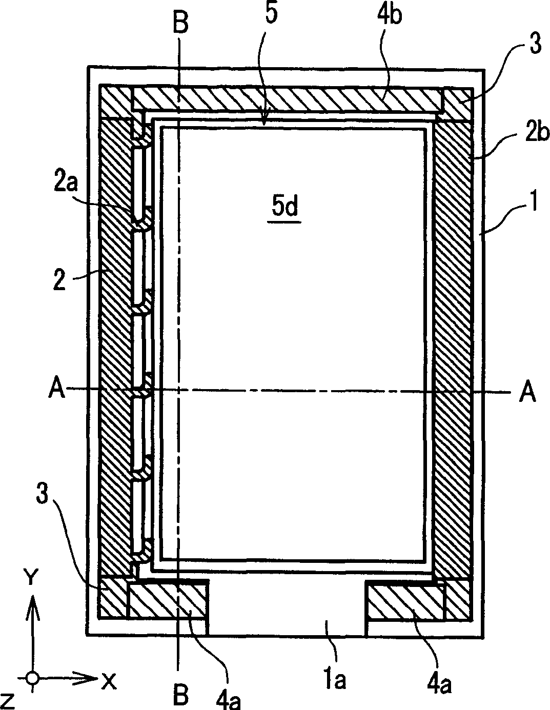
[0037] The liquid crystal display device of the present invention is an edge-light type liquid crystal display device in which a light guide plate is stacked on the back of a liquid crystal display panel, and light sources such as linear lamps and light emitting diodes are arranged on the edge of the light guide plate.

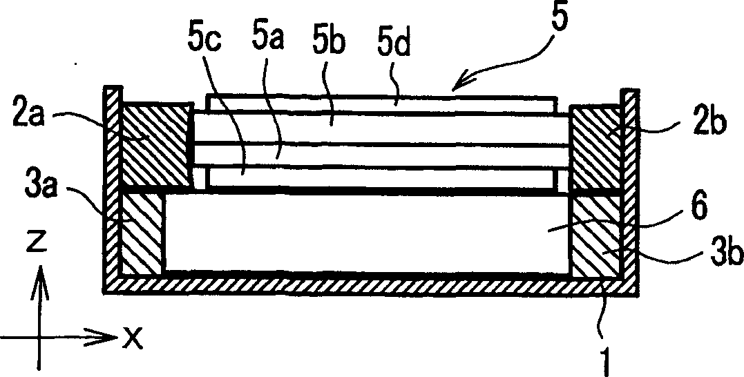
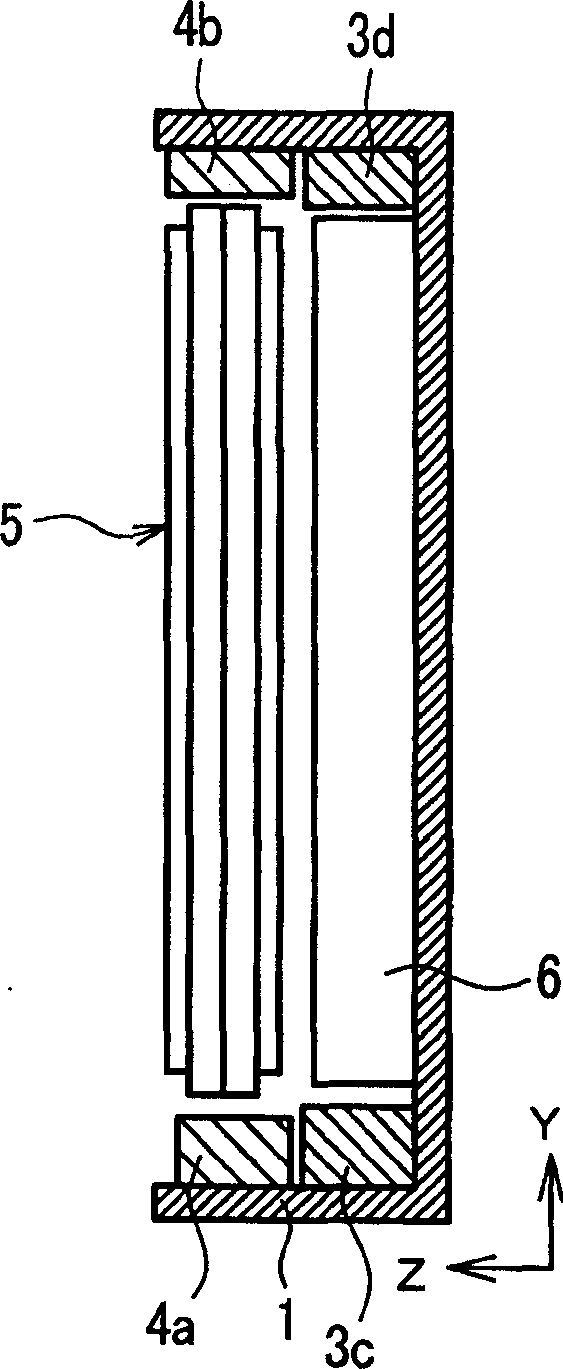
[0038] Figure 1A , Figure 1B and Figure 1C It is an explanatory diagram of Embodiment 1 of the liquid crystal display device of the present invention, Figure 1A for the floor plan, Figure 1B for along Figure 1A A profile of the A-A line, while Figure 1C for along Figure 1A Sectional view of the B-B line. exist Figure 1A , Figure 1B and Figure 1CAmong them, the reference numeral 1 is the metal frame, 2 is the first part of the resin spacer, ...


PUM


Abstract

The present invention provides a liquid crystal display device which can enlarge an effective display region without lowering a light quantity and can reduce a thickness and a weight thereof. A thin-film spacers having resiliency is arranged in the inside of a metal frame for holding a liquid crystal display panel. The spacer includes protrusions and a liquid crystal display panel is fixed by utilizing the resiliency of the protrusions. Further, by using resin material having high reflectance as a material of the spacer, it is possible to suppress the leaking of light from a light guide plate so that the lowering of luminance of the liquid crystal display device can be obviated.

Description

technical field [0001] The present invention relates to a liquid crystal display device in which a liquid crystal display panel and a metal frame with a backlight as an illumination light source are assembled on the back, and in particular relates to a liquid crystal display device capable of enlarging the effective display area and effectively utilizing the backlight while reducing thickness and weight A liquid crystal display device that improves brightness by illuminating light. Background technique [0002] A liquid crystal display device is a device that forms an electronic latent image on a liquid crystal display panel and visualizes the electronic latent image by illuminating light. There are known devices that utilize external light as an illumination light device and that incorporate an illumination light source that irradiates light on the back or front of a liquid crystal display panel. For liquid crystal display devices used as display means for small electronic...

Claims


Application Information

Patent Timeline
IPC IPC(8): G02F1/1333F21V8/00G02F1/13G02F1/1335G09F9/00G09F9/35
CPCG02F2201/503G02F2201/46G02F1/133308G02F1/1333
Inventor 伊藤贤橋本慎也
Owner JAPAN DISPLAY INC
Why Eureka
Try Eureka