
Manual rotary devices of sewing machines

A technology of rotating device and sewing machine, which is applied in the direction of sewing machine protection device, sewing machine control device, sewing machine components, etc., which can solve the problems of difficult manual operation and fastening state, and achieve good heat dissipation effect

Inactive Publication Date: 2003-09-03
PEGASUS SEWING MACHINE MFG
View PDF1 Cites 4 Cited by
  • Summary
  • Abstract
  • Description
  • Claims
  • Application Information

AI Technical Summary

Problems solved by technology

[0003] However, in the manual rotation device of the sewing machine constituted like this, because the output shaft of the sewing machine motor and the manual pulley shaft are arranged in a straight line, the manual pulley shaft deviates more to the side than the operator's sewing position, and it is difficult to perform manual rotation. operational problems
In addition, if an elastic member that separates the engagement plate of the manual pulley shaft from the engagement plate of the sewing machine motor is arranged, it becomes difficult to maintain the engagement state of the two plates.

Method used


Image

  • Manual rotary devices of sewing machines
  • Manual rotary devices of sewing machines
  • Manual rotary devices of sewing machines

Examples


Embodiment Construction

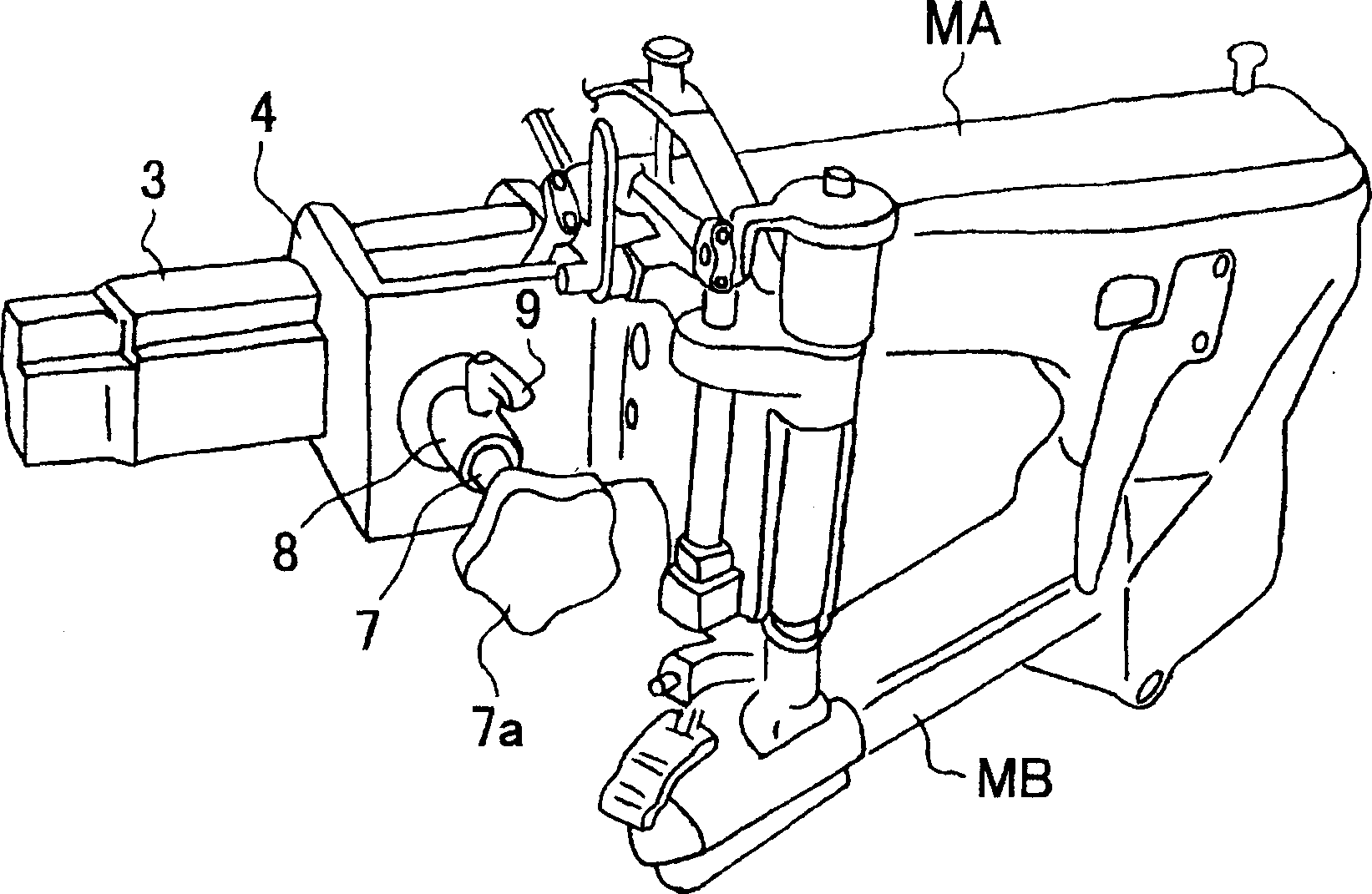
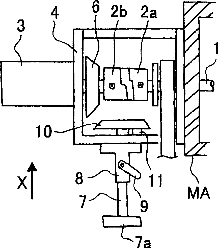
[0010] Embodiments of the present invention will be described below using the drawings. The sewing machine arm MA extends in a direction intersecting the longitudinal direction of the sewing machine head MB, and the operator stands on the right side of the continuation of both, and performs sewing work facing the longitudinal direction of the sewing machine head MB. The upper shaft 1 is fitted in the sewing machine arm MA, and is connected to a lower shaft (not shown) included in the sewing machine head MB via a link or the like. The upper shaft 1 is connected to the sewing machine motor 3 through couplings 2a, 2b. The sewing machine motor 3 is fixed to a bracket 4 attached to the sewing machine arm MA, and is located outside the sewing machine arm MA. The output shaft 5 of the sewing machine motor 3 has a bevel gear 6 (clutch plate).

[0011] A bearing 8 for supporting the manual pulley shaft 7 is provided on the front surface of the bracket 4 . The manual pulley shaft 7 e...


PUM


Abstract

To provide a manual rotation device, capable of reducing the occurrence of an injury near a manually operating pulley during the drive of a sewing machine and improving the operability of the manually operated pulley. This manual rotation device of a sewing machine is provided with an upper shaft cased in a sewing machine, a sewing machine motor having an output shaft of a clutch plate and connected to the upper shaft through a coupling, and a manually operating pulley shaft having an engagement plate engaged with the clutch plate of sewing machine motor and adapted to manually rotate the upper shaft. An output shaft of the sewing machine motor is made intersect perpendicularly to the manual operated pulley shaft.

Description

technical field [0001] The present invention relates to a manual rotation device of a sewing machine for easily performing operations such as threading by manually rotating an upper shaft connected to a sewing machine motor. technical background [0002] Conventionally, as a manual rotation device of a sewing machine, it has been widely known that, as shown in Unexamined Publication No. 5-31779, it is performed using a manual pulley disposed on a sewing machine arm. The manual pulley is fixed on one end of the manual pulley shaft for the convenience of manual operation. The other end of the manual pulley shaft has a tie plate (clutch plate), and the manual pulley shaft is rotatably and slidably supported on the bearing of the sewing machine arm. The clutch plate of the manual pulley shaft can be disengaged from the clutch plate attached to the output shaft of the sewing machine motor. When the clutch plate is engaged with the clutch plate, the rotation operation of the manu...

Claims


Application Information

Patent Timeline
IPC IPC(8): D05B69/34D05B83/00
Inventor 高田隆板东进
Owner PEGASUS SEWING MACHINE MFG
Learn More