Flue diluted and mixed turbulent flow stepped sampler

A technique of hierarchical sampling and turbulent flow, applied in the direction of sampling devices, etc.

Inactive Publication Date: 2003-09-10
NANKAI UNIV
View PDF0 Cites 7 Cited by
  • Summary
  • Abstract
  • Description
  • Claims
  • Application Information

AI Technical Summary

Problems solved by technology

[0008] The present invention is specially designed to overcome the defects of various...

Method used


Image

  • Flue diluted and mixed turbulent flow stepped sampler
  • Flue diluted and mixed turbulent flow stepped sampler
  • Flue diluted and mixed turbulent flow stepped sampler

Examples


Embodiment

[0036] Specific sampling steps:

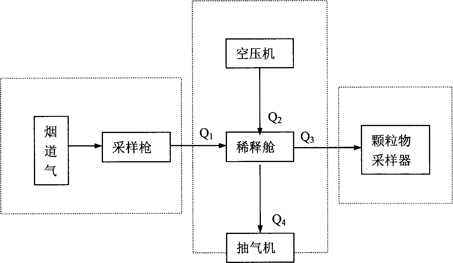
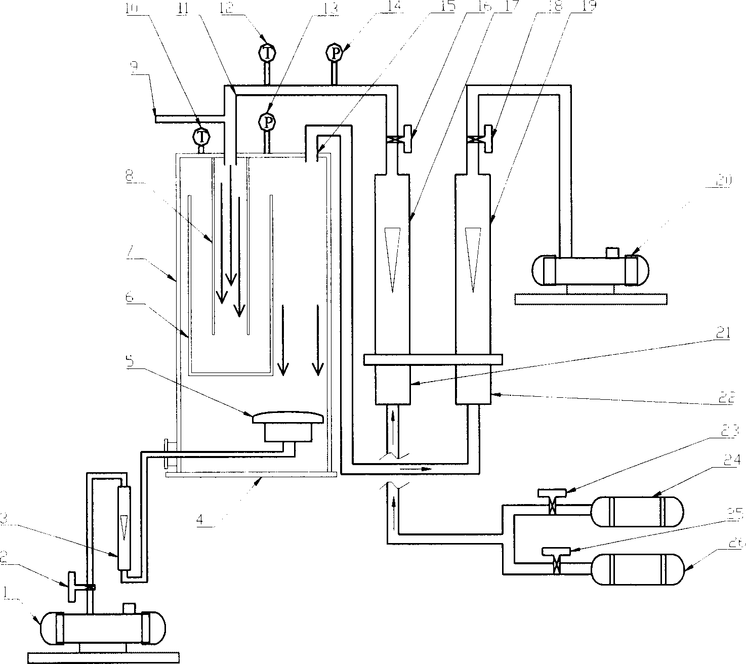
[0037] (1) Close the flue gas inlet valve 9, start the air compressors 24 and 26, adjust the compressor air valves 23, 25 and 16, so that a certain flow of dry and clean compressed air enters the dilution cabin, and record the incoming air flow Q 2 .

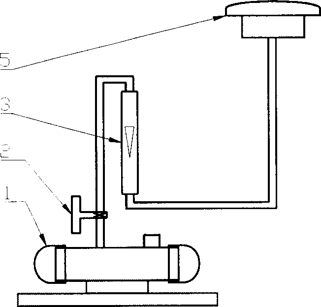
[0038] (2) Start the sampling vacuum pump 1 and adjust the exhaust valve 2 to adjust the flow meter 3 to a predetermined flow value. The sampling membrane with the cutting head installed is used for sampling at this flow rate.

[0039](3) Start the exhaust vacuum pump 20, adjust the exhaust valve 18, adjust the pressure gauge 13 on the dilution chamber loam cake to zero, and record the flow of the flowmeter (15).

[0040] (4) Open the flue gas inlet valve (9), mainly adjust the valve (18) and adjust other valves, so that the flue gas enters the dilution chamber according to a certain flow rate, and makes the pressure gauge 13 be zero. At this time, the air intake and exhaust of the dilution ch...


PUM


Abstract

The present invention relates to fume sampler, is especially diluted and mixed flue turbulent flow stepped sampler for collecting particle containing sample exhausted from fixed source, and belongs to environment monitoring technology. The present invention is based on available flue dust sampler and environment air particle matter sampler and has one increased diluting bin and corresponding pressure balancing air path. The present invention can sample different particle matter exhausted by fixed source and of different particle sizes in equal speed while monitoring. Particle sample of different particle size range may be collected in the physical and chemical conditions near the truc condition when flue dust enters environment air.

Description

technical field [0001] The invention relates to a smoke and dust sampler, in particular to a flue dilution mixed turbulent graded sampler for collecting particulate matter samples in the mixed gas of flue gas discharged from a fixed source and ambient air, and belongs to the technical field of environmental monitoring. Background technique [0002] Particles emitted from fixed sources of pollution exist in the form of aerosols and are one of the main sources of particles in the ambient air. Use the flue sampler to obtain particulate matter samples emitted by fixed pollution sources, and study the particle size distribution and chemical composition of particulate matter of different particle sizes, which is useful for monitoring: the degree of pollution of ambient air, the degree of impact on human health, and whether the pollution control measures adopted are appropriate etc. have important practical value. [0003] At present, there are many manufacturers producing flue sa...

Claims


Application Information

Patent Timeline
IPC IPC(8): G01N1/22G01N1/24
Inventor 朱坦郭光焕白志鹏葛苏
Owner NANKAI UNIV
Why Eureka
Try Eureka