
Ultrasonic pulverized coal sampling system

A sampling system, ultrasonic technology, applied in sampling, sampling devices, instruments, etc., can solve problems such as uneven distribution of coal powder fineness, increased device cost and complexity, unsatisfactory coal powder sampling effect, etc., to achieve good results Sampling efficiency, enhanced retarding effect

Pending Publication Date: 2022-02-01
XIAN THERMAL POWER RES INST CO LTD +1
View PDF0 Cites 0 Cited by
  • Summary
  • Abstract
  • Description
  • Claims
  • Application Information

AI Technical Summary

Problems solved by technology

Among them, the direct blowing pulverization system has the advantages of small footprint, convenient combination of coal mills, high safety during operation, and low power consumption for pulverization, but the disadvantage lies in the fineness distribution of pulverized coal in the pulverization pipe uneven
However, the constant velocity sampling system using the cyclone separator has the following problems: 1), the constant velocity sampling system using the cyclone separator has higher requirements on the stability and continuity of the air extraction airflow, and in the powder conveying pipe When the flow rate fluctuates greatly and the powder flow rate of the pulverizing system changes significantly, the sampling efficiency of the pulverized coal will be reduced; 2), the constant-speed sampling system using the cyclone separator needs to adopt a special The micro cyclone separator increases the cost and complexity of the device, and the sampling effect of pulverized coal is not satisfactory

Method used


Image

  • Ultrasonic pulverized coal sampling system
  • Ultrasonic pulverized coal sampling system
  • Ultrasonic pulverized coal sampling system

Examples


Embodiment Construction

[0027] In order to enable those skilled in the art to better understand the solutions of the present invention, the following will clearly and completely describe the technical solutions in the embodiments of the present invention in conjunction with the drawings in the embodiments of the present invention. Obviously, the described embodiments are only It is an embodiment of a part of the present invention, but not all embodiments. Based on the embodiments of the present invention, all other embodiments obtained by persons of ordinary skill in the art without making creative efforts shall fall within the protection scope of the present invention.

[0028] It should be noted that the terms "first" and "second" in the description and claims of the present invention and the above drawings are used to distinguish similar objects, but not necessarily used to describe a specific sequence or sequence. It is to be understood that the data so used are interchangeable under appropriate ...


PUM

PropertyMeasurementUnit
thicknessaaaaaaaaaa

Abstract

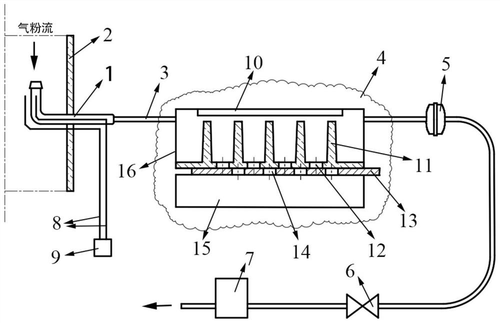
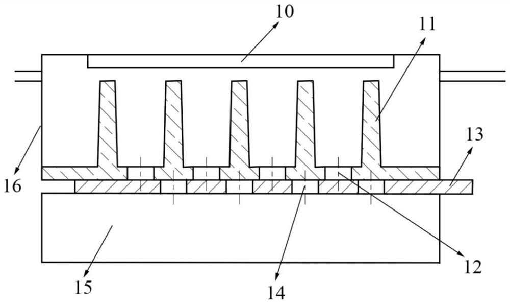
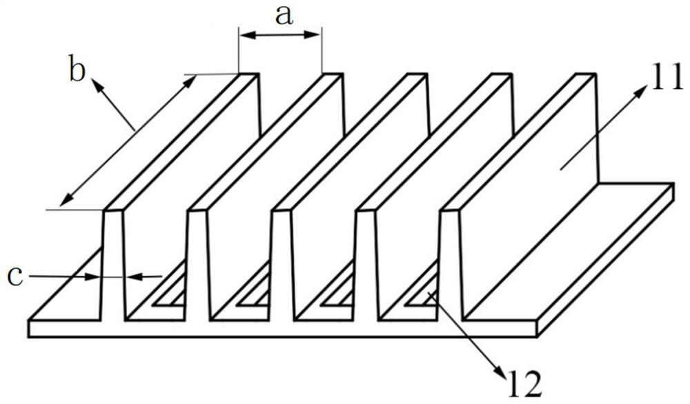
The invention belongs to the field of coal processing, and discloses an ultrasonic pulverized coal sampling system which comprises a sampling pipe, an ultrasonic pulverized coal collector, a regulating valve, an air extracting pump, a pressure measuring pipe assembly and a pressure meter. The ultrasonic pulverized coal collector comprises an ultrasonic sealing belt, a spoiler, a movable plate, a pulverized coal collecting box and a shell. The pressure measuring pipe assembly comprises a first pressure measuring pipe and a second pressure measuring pipe. The sampling pipe is sequentially connected with an ultrasonic pulverized coal collector, a regulating valve and an air extracting pump; the ultrasonic sealing belt is connected with the inner wall of the top of the shell; a plurality of flow blocking bulges and upper powder discharging holes are formed in the spoiler; the movable plate is located between the spoiler and the pulverized coal collecting box, and a plurality of lower pulverized coal discharging holes are formed in the movable plate; one end of the first pressure measuring pipe is located in the sampling pipe, and the first pressure measuring pipe and the second pressure measuring pipe are both connected with the pressure gauge; the ultrasonic sealing belt is used to generate ultrasonic waves. Pulverized coal sampling work of the direct-fired coal pulverizing system under the variable working condition can be better achieved, and the sampling efficiency is better in the direct-fired coal pulverizing system under the small-flow working condition.

Description

technical field [0001] The invention belongs to the field of coal processing and relates to an ultrasonic coal powder sampling system. Background technique [0002] Coal-fired thermal power plants dominate. Generally speaking, in the process of coal combustion, the finer the pulverized coal is, the more fully the combustion will be, and the higher the combustion efficiency of the boiler will be. However, the finer the pulverized coal, the higher the cost of coal grinding, and it is easy to cause the pulverized coal to explode. Therefore, it is necessary to keep the fineness of pulverized coal within a reasonable range. During the operation of coal-fired power plants, it is necessary to measure and analyze the fineness of pulverized coal in real time. According to the measurement results, compare the optimal range of pulverized coal fineness, and constantly adjust the operating conditions of the pulverizing system so that the entire coal-fired unit can operate under efficie...

Claims


Application Information

Patent Timeline
Patent Type & Authority Applications(China)
IPC IPC(8): G01N1/22
CPCG01N1/2247G01N1/2205G01N2001/225
Inventor 马晨曦李崇晟陈建平吴智群何新
Owner XIAN THERMAL POWER RES INST CO LTD
Learn More