Rotary piston machine

A technology of rotating piston and piston, applied in the direction of rotating or oscillating piston engine, oscillating piston machine, internal combustion piston engine, etc. The effect of large environmental protection use, large working speed range and large flow rate

Inactive Publication Date: 2003-09-17
姚平
View PDF0 Cites 7 Cited by
  • Summary
  • Abstract
  • Description
  • Claims
  • Application Information

AI Technical Summary

Problems solved by technology

Because these structures have complex structure, complex process, high production cost, large volume and mass, relatively small ratio of working

Method used


Image

  • Rotary piston machine
  • Rotary piston machine
  • Rotary piston machine

Examples


Example Embodiment

[0042]1. The basic structure and working principle of the rotary piston machine:
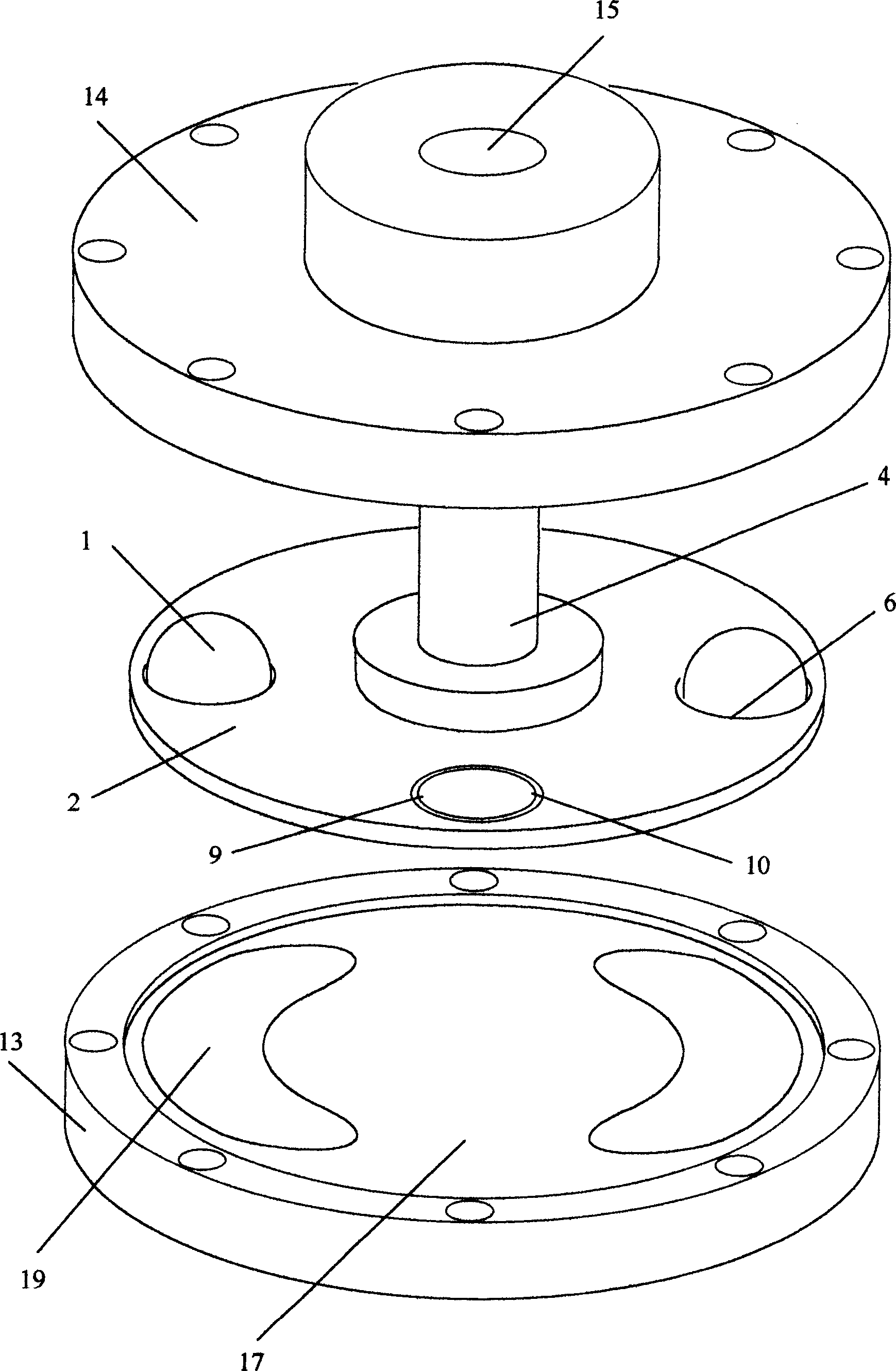
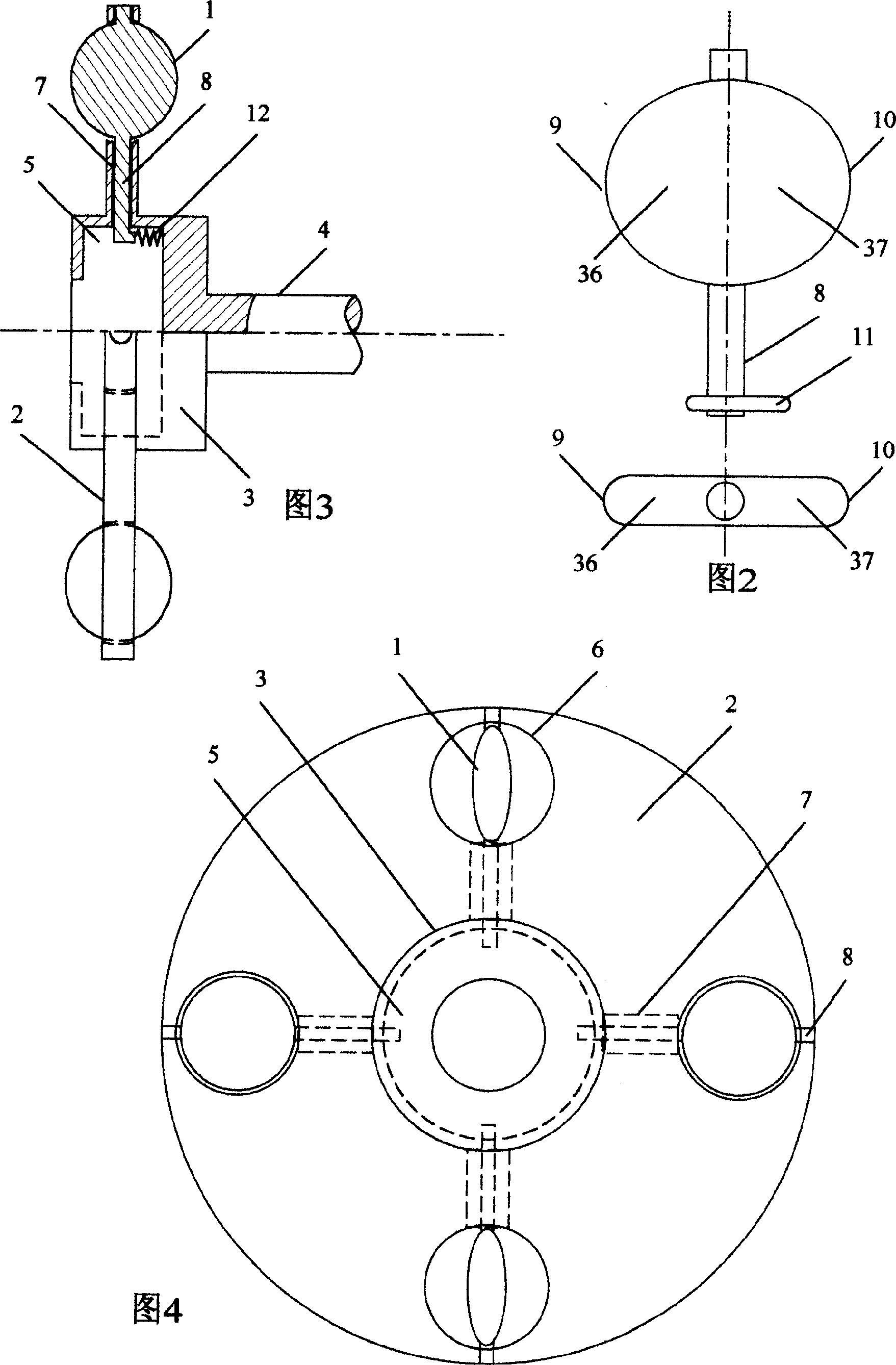
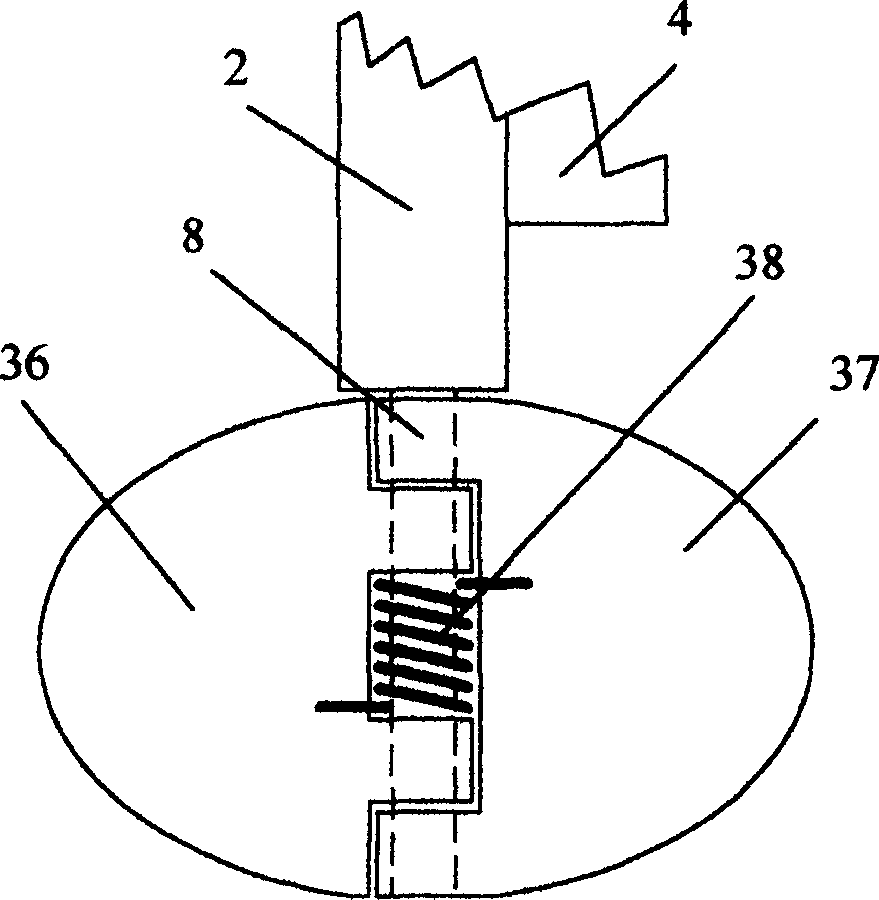
[0043] in figure 1 Among them, the plate-shaped piston (1) is a symmetrical plate-shaped structure. There is a piston shaft on the symmetry axis of the plate-shaped piston (1). The plate-shaped piston (1) has a left edge (9) and a right edge relative to the axis of the piston shaft. (10). The main shaft (4) is cylindrical, the outer circumference of the main shaft (4) is provided with a piston frame (2), the piston frame (2) is also cylindrical, and the piston frame (2) is connected to the main shaft (4) and is on the same central axis Synchronous rotation on the top. A number of piston holes (6) passing through its thickness are distributed on the circular plane of the piston frame (2). The radial distance of each piston hole (6) on the piston frame (2) is the same, and the plate-shaped piston (1) The piston shaft is supported in the piston hole (6) on the piston carrier (2). The plate-shaped pist...


PUM


Abstract

A rotary piston unit for IC engine, water turbine, steam turbine, water pump, air compressor, etc is composed of disk-shaped piston holder on mainshaft, multiple plate pistons running directionally around mainshaft in planetary mode, and two semi-cylinders on two end faces of planetary piston to form a piston space with alternative big and small cross-sections. The left part and right part of each plate piston sequentially and periodically come in said piston space to form piston effect, realizing the conversion between fluid energy and mechanical energy.

Description

Technical field [0001] The invention relates to the field of rotary piston machinery in which solid mechanical energy and fluid energy are mutually converted. Background technique [0002] In the prior art, the function of the water turbine and the steam turbine is to convert fluid energy into mechanical energy (torque of directional rotation), which has been realized in the prior art and has high efficiency. However, for the environment of low water head, low flow, low pressure or low speed, the working efficiency of water turbine and steam turbine will be greatly reduced; in the prior art, the function of water pump and fan is to convert mechanical energy into fluid energy. A little prior art has also been realized, but for the environment of low rotating speed, the working efficiency of water pump and blower fan just will reduce greatly. The reason is that during the rotation of these machines, the casing (cylinder) and the blade (piston) do not cooperate with each other...

Claims


Application Information

Patent Timeline
IPC IPC(8): F01C9/00F02B53/02F04C9/00F04C21/00
CPCY02T10/12
Inventor 姚平
Owner 姚平
Why Eureka
Try Eureka