Camera apparatus

A camera device and camera element technology, applied in installation, image communication, television, etc., to achieve the effects of improving light-shielding properties, improving bonding strength, and improving light leakage capabilities

Inactive Publication Date: 2003-09-17
CASIO COMPUTER CO LTD
View PDF1 Cites 9 Cited by
  • Summary
  • Abstract
  • Description
  • Claims
  • Application Information

AI Technical Summary

Problems solved by technology

[0005] However, in the existing imaging device, the holder on which the light receiving unit is fixed is fixed to the rear end of the lens frame with bolts. Therefore, when the bolts are not sufficiently tightened, or when the lens frame and the holder cannot be tightly bonded, Light that leaks from the joint between the holder and the lens frame may enter the CCD imaging element
In addition, although it is considered to use adhesive instead of bolts to join the lens frame and holder, at this time, the light leaked from the adhesive layer formed by the adhesive may also enter the CCD imaging element.

Method used


Image

  • Camera apparatus
  • Camera apparatus
  • Camera apparatus

Examples


no. 1 Embodiment

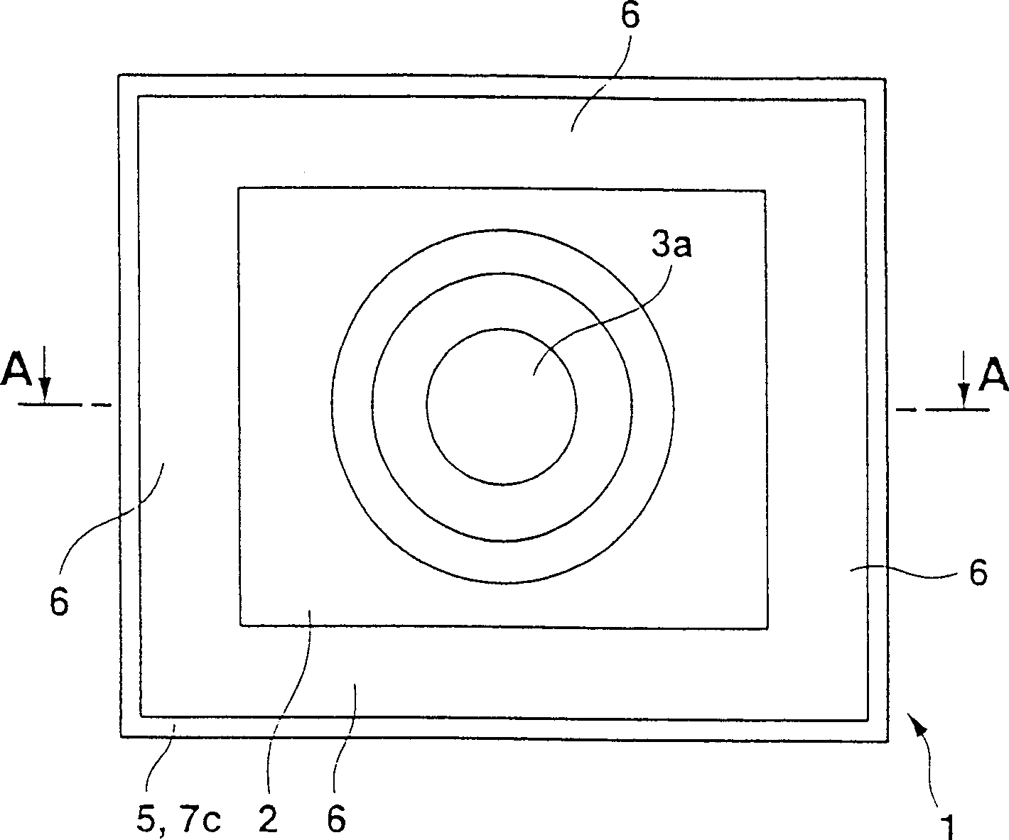
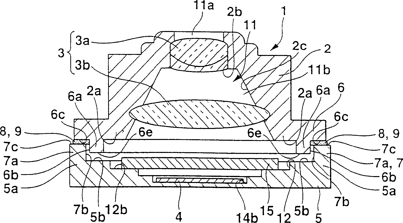
[0034] As shown in Figure 1, the imaging device 1 of the first embodiment is an imaging device using a pan-focus camera (pan-focus camera) or the like, and has: a lens frame 2, an imaging lens 3 for photographing an object is arranged inside it; Outer package (picture element holder) 5, the CCD photoelectric sensor (image pickup element) 4 that photoelectric conversion is carried out to the subject image that is taken by camera lens 3 is installed in its inside; And lens frame 2 and CCD outer package 5 are joined mutually . In addition, in the following description, the subject side of the camera at the time of shooting, that is, the upper side in FIG.

[0035] The lens frame 2 has a substantially rectangular cylindrical shape and has a hollow portion 11 communicating in the optical axis direction, that is, the vertical direction in FIG. 1( b ). The hollow portion 11 has: a first hollow portion 11a, which is surrounded by a substantially cylindrical first inner wall 2b; a sec...

no. 2 Embodiment

[0050] Next, the second embodiment will be described.

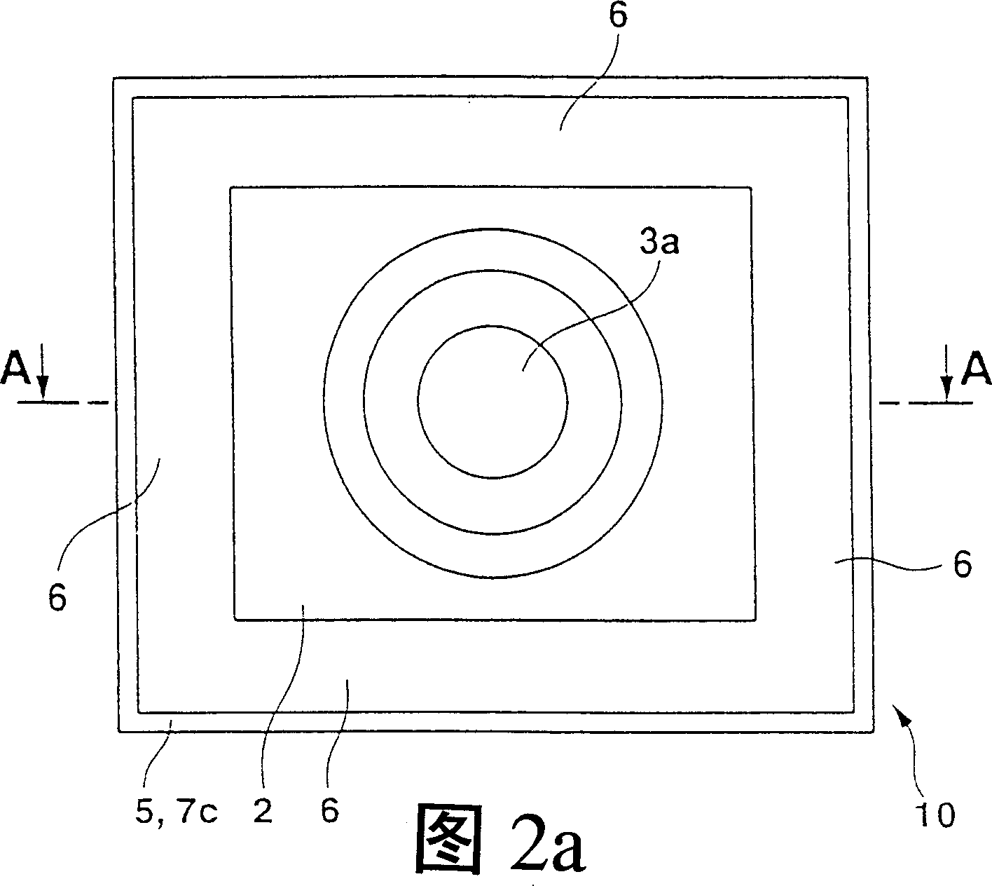
[0051] The imaging device 10 of the second embodiment, as shown in FIG. 2, is an imaging device in which the positions of the first convex portion 6a on the outside and the second convex portion 7a on the inside of the first embodiment are changed from each other. The same as the first embodiment. Therefore, in the imaging device 10, the same constituent elements as those of the imaging device 1 of the first embodiment are assigned the same reference numerals, and description thereof will be omitted.

[0052] On the outer edge of the end surface 6c of the flange portion 6, a first convex portion 6a protruding toward the CCD outer package 5 side is formed extending from the peripheral portion 2a of the lens frame 2, as in the first embodiment.

[0053] On the edge of the front of the CCD outer package 5, there is provided a stepped portion 5c recessed to the rear, the height of which is approximately equal to the height o...

no. 3 Embodiment

[0060] Next, refer to image 3 The third embodiment will be described.

[0061] In the imaging device 21 of the third embodiment, the lens frame 2 and the imaging lens 3 disposed therein, the CCD outer package (imaging element holder) 5, the CCD photosensor (imaging element) 4 disposed therein, and the OLPA 15 etc. are the same as those of the first and second embodiments, therefore, while simplifying their illustrations, the same constituent elements as those of the imaging devices 1 and 10 of the first and second embodiments are given the same reference numerals, and Its description is omitted.

[0062] The difference between the third embodiment and the first and second embodiments is the structure of the lens frame joint part 6 and the outer package joint part (holder joint part) 7, so these differences will be described in detail below.

[0063] That is, ribs (protrusions) 18 are formed on the end surface 6c of the lens frame joint portion 6 to extend along the peripher...


PUM


Abstract

PROBLEM TO BE SOLVED: To provide an imaging apparatus capable of shutting off a light leaked from a joining face between a holder and a lens frame to an image device.

SOLUTION: The imaging apparatus 1 is characterized in that the lens frame 2 and the imaging device holder 5 are joined together, a first projection 6a projected toward the imaging device holder 5 is formed to a lens frame joining part 6 of the lens frame 2 joined with the imaging device holder 5 so as to extend to a circumferential edge 2a of the lens frame 2, and a second projection 7a projected toward the lens frame 2 is formed to a holder joining part 7 of the imaging device holder 5 joined with the lens frame 2 so as to extend to a circumferential edge 5a of the imaging device holder 5, and the lens frame 2 and the imaging device holder 5 are joined in a way that the first and second projections 6a, 7a are overlapped in a direction in crossing with the projected directions of the first and second projections 6a, 7a in order to solve the task above.

COPYRIGHT: (C)2004,JPO

Description

technical field [0001] The invention relates to an imaging device for photographing an object. Background technique [0002] Such as Figure 7 As shown, the existing imaging device 100 used in cameras (Camera) etc. has: the imaging lens 30 composed of two lenses 30a, 30b installed in the lens frame 20; (optical filter) 40 ; and a light receiving unit 50 provided behind the optical filter 40 . [0003] The optical filter 40 is an optical filter such as a crystal optical filter, an infrared cut filter, etc. matched with the characteristics of the CCD (charge-coupled device) imaging element 50a. Planar components. In addition, this filter 40 is inserted into a filter mounting portion 20 a provided at the rear of the lens frame 20 . [0004] The light receiving unit 50 is composed of a CCD imaging element 50a, an outer package (package) 50b that holds the CCD imaging element 50a, and a sealing glass (glass) 50c that seals the CCD imaging element 50a in the outer package 50b a...

Claims


Application Information

Patent Timeline
Patent Type & Authority Applications(China)
IPC IPC(8): G02B7/02G03B19/02H04N5/225
Inventor 铃木幸夫高桥泰藏
Owner CASIO COMPUTER CO LTD
Why Eureka
Try Eureka