Nuclear reactor control rod hydraulic driving system

A driving system and control rod technology, which is applied in the field of structural design of nuclear reactor control rod hydraulic drive system, can solve problems such as the complexity of driving characteristics, and achieve the effects of enhancing safety, avoiding rod popping accidents, and large overload capacity

Inactive Publication Date: 2003-09-17
TSINGHUA UNIV
View PDF1 Cites 30 Cited by
  • Summary
  • Abstract
  • Description
  • Claims
  • Application Information

AI Technical Summary

Problems solved by technology

[0006] The purpose of the present invention is to address the deficiencies and defects of the prior art, and provide a new control rod hydraulic drive system for an integrated nuclear reactor, so that it can solve the hydraulic drive control rod system in the prior art. The shortcoming of the complexity of the driving characteristics caused by the change of working conditions enables the control rod to be accurately positioned and moved step by step, while retaining the advantages of the magnetic lifter grasping mechanism drive; at the same time, it overcomes the long transmission line and avoids the occurrence of rod spring accidents

Method used


Image

  • Nuclear reactor control rod hydraulic driving system
  • Nuclear reactor control rod hydraulic driving system
  • Nuclear reactor control rod hydraulic driving system

Examples


Embodiment Construction

[0017] The specific structure, working process and embodiments of the present invention will be described in detail below in conjunction with the accompanying drawings.

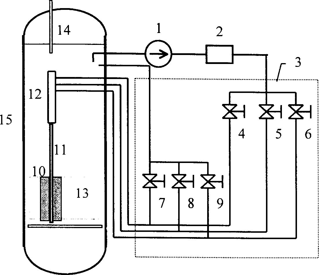
[0018] The hydraulic drive system of the present invention is as figure 1 As mentioned above, it mainly includes the core 13, the control rod 10, the drive shaft 11, the pressure vessel 15, the rod position measurement 14, the circulating water pump 1, the filter 2, the combination valve 3 and the like. The combination valve 3 is made up of three normally closed electromagnetic valves (4, 5, 6) connected in parallel and three normally open electromagnetic valves (7, 8, 9) connected in parallel. The water outlets of the three normally closed solenoid valves are respectively connected with the water inlets of the three pressure water cylinders, and the water outlets of the three normally open solenoid valves are connected with the pressure vessel 15 .

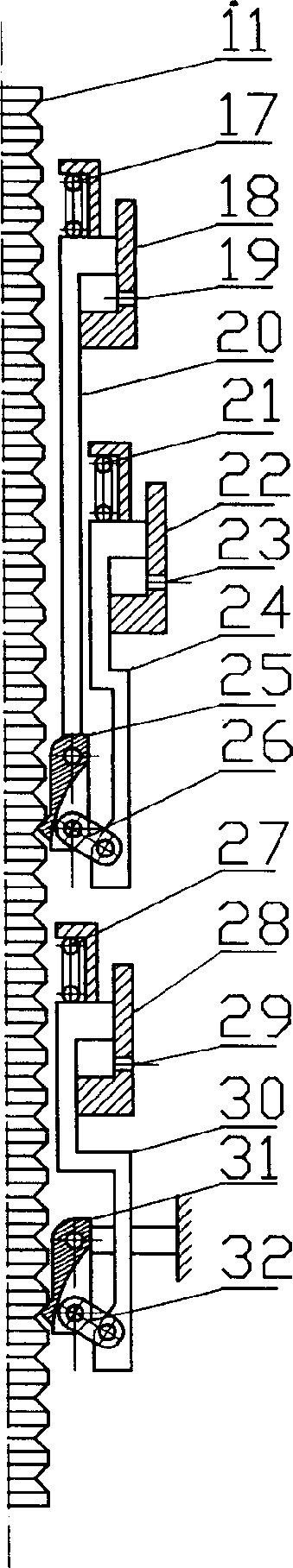
[0019] Drive mechanism 12 of the present invention is mad...


PUM


Abstract

A hydraulic drive system for the control rods of nuclear reactor features that its drive mechanism has three hydraulic cylinders and two pinned jaw mechansms, its combined valve is composed of 3 parallel electromagnetic valves opened normally and 3 parallel electromagnetic valves closed normally, and said hydraulic cylinders are driven by the static pressure of water. Its advantages are correct location and step movement, high over-load power, short transfer distance, and high safety.

Description

technical field [0001] The invention relates to a structural design of a built-in nuclear reactor control rod hydraulic drive system, which belongs to nuclear reactor engineering [0002] technology field. Background technique [0003] The control rod drive mechanism of nuclear reactor is the most critical safety equipment of the reactor, which is responsible for the important functions of the reactor starting, power regulation and shutdown. The control rod driving mechanism is generally located outside the reactor pressure vessel, such as the PWR control rod driving mechanism*magnetic lifter is located on the pressure vessel cover, the advanced boiling water reactor control rod driving mechanism*micro-motion control rod driving mechanism is located at the bottom of the pressure vessel, accounting for about 1 / 3 of the height of the entire reactor is called an external drive. The biggest disadvantage of the external drive is that the transmission line is long, which increas...

Claims


Application Information

Patent Timeline
Patent Type & Authority Applications(China)
IPC IPC(8): G21C7/16
CPCY02E30/30
Inventor 薄涵亮杨巾农姜胜耀郑文祥
Owner TSINGHUA UNIV
Why Eureka
Try Eureka