
Dynamic multiple wavelength grouping ring transmission system

A transmission system and multi-wavelength technology, which is applied in the field of dynamic multi-wavelength packet ring transmission system, can solve the problems of impracticality, large-capacity network cost, network scalability limitation, etc., and achieve performance improvement, economical network construction cost, good The effect of network scalability

Inactive Publication Date: 2003-10-01
SHANGHAI JIAO TONG UNIV
View PDF0 Cites 4 Cited by
  • Summary
  • Abstract
  • Description
  • Claims
  • Application Information

AI Technical Summary

Problems solved by technology

There is no doubt that the cost of using this structure to build a large-capacity network is quite large, and it is actually not practical
[0008] Moreover, this structure also brings another problem. When the network has multiple logical rings and the number of nodes in the ring is considerable (such as dozens), since the packets are forwarded point by point through each intermediate node, the accumulated forwarding The delay is also considerable, especially when a network failure requires protection switching and detour transmission
[0009] According to the above analysis, the existing packet ring transmission system has limitations in network scalability, and the disadvantages are especially obvious when the network scale increases

Method used


Image

  • Dynamic multiple wavelength grouping ring transmission system
  • Dynamic multiple wavelength grouping ring transmission system
  • Dynamic multiple wavelength grouping ring transmission system

Examples


Embodiment Construction

[0023] In order to better understand the technical solution of the present invention, a detailed description is given below in conjunction with the accompanying drawings and embodiments. The figures and examples do not imply a limitation of the invention.

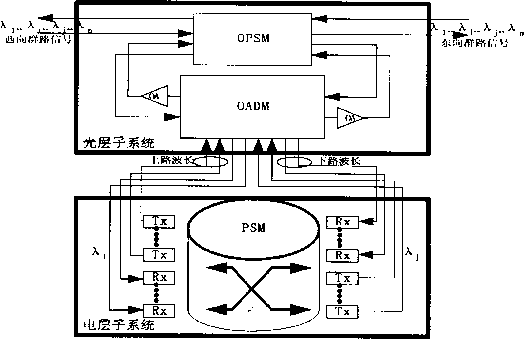
[0024] figure 1It is a functional block diagram of the node structure of the system of the present invention. The node is composed of an optical layer subsystem and an electrical layer subsystem. The optical layer subsystem includes an optical layer protection switching module (OPSM), an optical amplifier (OA) and an optical add-drop multiplexer (OADM). The electrical layer subsystem includes a line receiving module. (Rx), Line Transmit Module (Tx) and Packet Switch Module (PSM). Optical layer group signal (λ 1 ..λ i ..λ j ..λ n ) first enters the optical layer protection switching module (OPSM) from the receiving link, and then connects with the optical add-drop multiplexer (OADM), and the drop wavelength signal (λ ...


PUM


Abstract

A dynamic multiwave length grouped ring transmission system is composed of an electric layer subsystem including line receiving module, line transmitting module and grouped exchanging module being connected with optical layer subsystem through internal wavelength up and downlink interfaces as well as an optical layer subsystem including optical layer protection, negating module, optical amplifierand optical add-drop multiplexer / demultiplexer. The line receiving / transmitting module finalizes adaption and conversion for signals of electric and optical layers; the grouped exchanging module transmits data to the line transmitting module after the second or the third layer being exchanged; the optical layer protection negating module realizes fast protective negation for optical layer group signal and the optical add-drop multiplexing module realize adding.

Description

Technical field: [0001] The present invention relates to a dynamic multi-wavelength packet ring transmission system. In the traditional elastic packet ring system, wavelength division multiplexing technology (WDM) is combined to increase the wavelength dynamic bypass function of the optical layer subsystem, so that the elastic packet ring system has good network expansion capabilities. The invention belongs to the technical field of broadband communication network. Background technique: [0002] With the rapid growth of Internet services, the construction of a new generation of broadband metropolitan area network to meet the needs of future network development has become a hot spot for investment in the telecommunications sector. In the construction of the broadband metropolitan area network, various solutions emerge, among which, the RPR (Resilient Packet Ring) solution being standardized by the IEEE802.17 working group is highly expected due to its unique advantages. [...

Claims


Application Information

Patent Timeline
IPC IPC(8): H04B10/032H04J14/02H04L12/40H04Q3/52
Inventor 欧阳勇曾庆济魏威
Owner SHANGHAI JIAO TONG UNIV
Learn More