Produce transformer and method for coupling working pressure to pressure sensor

A pressure sensor, working pressure technology, applied in the direction of converting sensor output, measuring fluid pressure through electromagnetic elements, measuring fluid pressure, etc., can solve the problems of isolation diaphragm deformation, welding ring and transmitter shell deformation, inaccurate results and other problems

Inactive Publication Date: 2003-10-08
ROSEMOUNT INC
View PDF2 Cites 31 Cited by
  • Summary
  • Abstract
  • Description
  • Claims
  • Application Information

AI Technical Summary

Problems solved by technology

[0005] Connection forces compressing the weld ring and the flange can deform or deflect parts of the weld ring and the transmitter housing
Additionally, connection forces can create stress in th

Method used


Image

  • Produce transformer and method for coupling working pressure to pressure sensor
  • Produce transformer and method for coupling working pressure to pressure sensor
  • Produce transformer and method for coupling working pressure to pressure sensor

Examples


Embodiment Construction

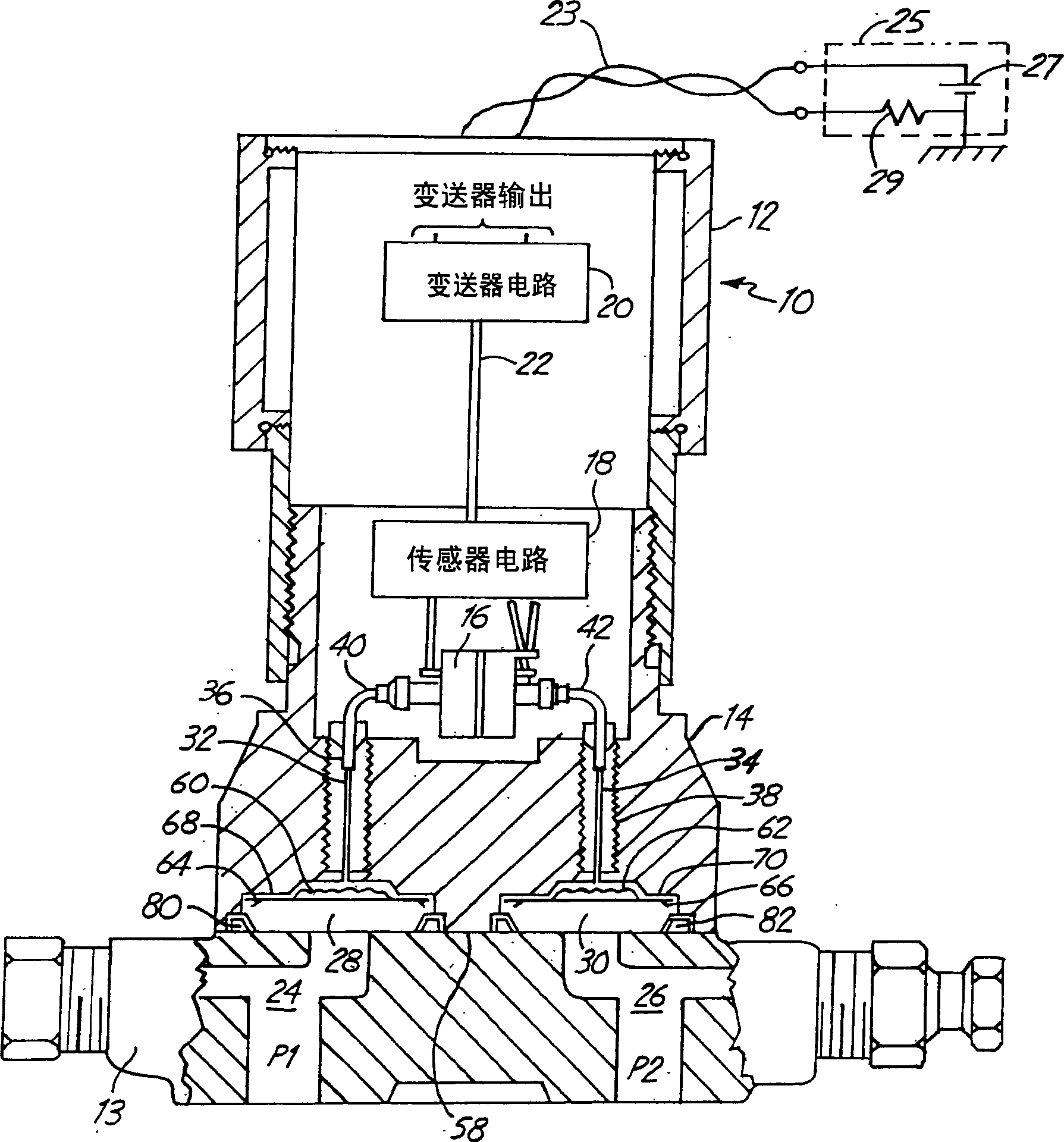
[0017] figure 1 A pressure transmitter 10 according to the invention is shown having a transmitter body 12 coupled to a flange (coplanar branch) 13 via a sensor housing 14 . Although the present invention shows Coplanar TM Type of working flange, but the present invention can use any form of flange, branch pipe or other joints that are suitable for receiving working fluid. Sensor housing 14 includes pressure sensor 16 , while transmitter body 12 includes transmitter circuitry 20 . Sensor circuitry 18 is coupled to transmitter circuitry 20 by communication bus 22 .

[0018] Transmitter circuitry 20 sends information related to working fluid pressure to working control loop 23, eg 4-20mA, HART, Filedbus, Profibus. Transmitter 10 communicates information related to working fluid pressure to a control chamber 25 or other device (not shown) coupled to working control loop 23 . The working control room 25 is designed with a power supply 27 and a resistor 29 . Transmitter 10 can...


PUM


Abstract

A process transmitter for measuring a process pressure includes a pressure sensor in a sensor housing. An isolation diaphragm which isolates fill fluid from process fluid is spaced apart from a process fluid seal. The spacing reduces deformation of the isolation diaphragm due to a mounting force.

Description

technical field [0001] The present invention relates to a process control device, and more particularly, to a work fitting for coupling a pressure transmitter to a working fluid. Background technique [0002] Industrial operations such as refineries, chemical plants, etc. use remote sensors called "transmitters" to detect various operating variables such as pressure, temperature, flow, etc. The sensed work variables are used to monitor and / or control the operation of the work. [0003] Transmitters that sense the pressure of the working fluid use a pressure sensor that is usually coupled to at least one isolating diaphragm. A transmitter is connected to the flange and includes an opening aligned to receive working fluid from the passage of the flange. The isolation diaphragm sits at the opening of the transmitter and isolates the pressure sensor from the fluid being sensed. This protects the sensor from damage or corrosion by the working fluid. Pressure is transmitted fr...

Claims


Application Information

Patent Timeline
IPC IPC(8): G01L19/06G01L9/00G01L19/00
CPCG01L19/0038G01L19/0046
Inventor 大卫·A·布罗登德布拉·K·泽勒
Owner ROSEMOUNT INC
Why Eureka
Try Eureka