Supercharge Your Innovation With Domain-Expert AI Agents!

Wave-division multiplexing passive optical fiber network system

A technology of passive optical fiber network and wavelength division multiplexing, which is applied in the field of passive optical fiber network system of wavelength division multiplexing

Inactive Publication Date: 2003-10-08
SAMSUNG ELECTRONICS CO LTD
View PDF0 Cites 6 Cited by
  • Summary
  • Abstract
  • Description
  • Claims
  • Application Information

AI Technical Summary

Problems solved by technology

However, this method has the very big disadvantage of
For example, conventional ATM-PON systems set limits on data transmission speeds (i.e., 155 Mbits per second for upstream channels and 622 Mbits per second for downstream channels)
Also, no international standards body has yet decided on the implementation of a data transmission speed of 1.25 Gigabit in both directions in an Ethernet-passive optical network

Method used


Image

  • Wave-division multiplexing passive optical fiber network system
  • Wave-division multiplexing passive optical fiber network system
  • Wave-division multiplexing passive optical fiber network system

Examples


Embodiment Construction

[0033] Preferred embodiments of the present invention will be described below with reference to the accompanying drawings. In the drawings, well-known functions, elements, devices or structures are not described in detail since they would obscure the invention in unnecessary detail.

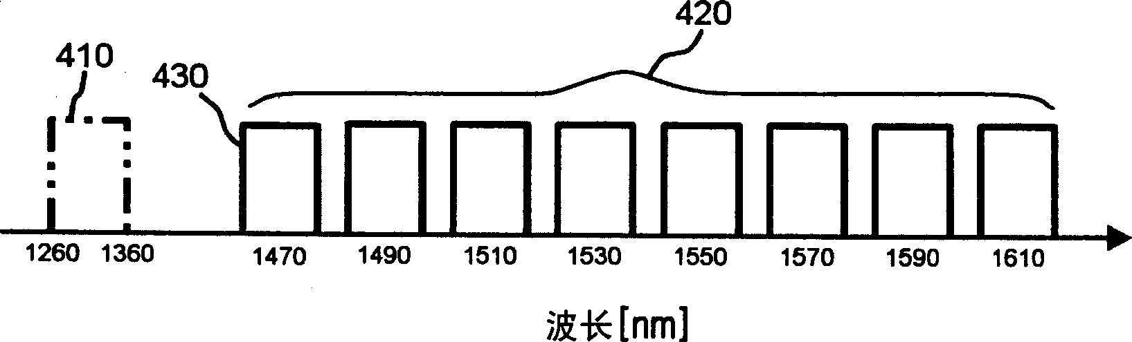
[0034] image 3 is a graph showing the wavelength allocation of a passive optical network system according to a preferred embodiment of the present invention. image 3 An upstream wavelength band 410 is depicted, and a downstream wavelength band of 1550 nm (or 1490 nm) with an additional bidirectional wavelength band 420 is depicted.

[0035] The wavelength allocated to the upstream wavelength band 410 falls within the range of 1260-1360 nm, and it is used as the wavelength band used by optical signals going from the fiber optic network elements to the fiber optic transmission terminals.

[0036] A wavelength band in the range of 1470-1610 nm is allocated to an additional bidirectional waveleng...


PUM


Abstract

A wavelength division multiplexing passive optical fiber network system includes: an optical fiber transmission terminal for transmitting downlink optical signals through optical fibers. A downstream optical signal is obtained by performing wavelength division multiplexing on downstream channels having mutually different wavelengths. The optical fiber transmission terminal also demultiplexes the uplink optical signal received through the optical fiber. The upstream optical signal includes first and second upstream channels having different wavelengths from each other. The system also includes a power divider, which is used to uniformly divide the power of the downstream optical signal received through the first port connected to the optical fiber, and is used to output the distributed optical signal through a plurality of second ports, and through the first port Output uplink optical signal. The upstream optical signal is a combination of the first and second upstream channels received from the plurality of second ports. The system also includes a plurality of fiber optic network elements for wavelength demultiplexing the downstream optical signal from the second port of the optical divider and for transmitting the first and second upstream channels to the optical divider.

Description

technical field [0001] The present invention generally relates to a passive optical fiber network, and more particularly relates to a wavelength division multiplexing passive optical fiber network system. technical background [0002] Various network configurations such as xDSL (x-Digital Subscriber Line), HFC (Hybrid Fiber Coaxial Cable), FTTB (Fiber To The Building), FTTC (Fiber To The Curb) or FTTH (Fiber To The Home) have been proposed, For configuring user networks from central offices to customer premises environments such as buildings and residences. [0003] These FTTx (i.e., FFTB, FTTC, FTTH) implementations can be divided into two categories: (1) Active FTTx using Active Optical Networks (AON), and (2) Passive FTTx using Passive Optical Networks (PON). Source FTTx. Because of the point-to-multipoint topology through passive components, the passive optical network is considered to be a future optical fiber subscriber network with good economic value. [0004] Typ...

Claims


Application Information

Patent Timeline
Patent Type & Authority Applications(China)
IPC IPC(8): H04B10/27H04B10/272H04J14/00H04J14/02H04L12/44
CPCH04J14/0226H04J14/0282H04J14/0246H04J14/0247H04J14/025H04J14/0252H04J14/02
Inventor 朴泰诚
Owner SAMSUNG ELECTRONICS CO LTD
Features
  • R&D
  • Intellectual Property
  • Life Sciences
  • Materials
  • Tech Scout
  • Unparalleled Data Quality
  • Higher Quality Content
  • 60% Fewer Hallucinations
Learn More