

Method for solving interlace by using error correction and motion compensation as well as its equipment
A technology of motion compensation and error correction, which is applied in the field of digital TV scanning format conversion, can solve the problems of high cost ratio, insufficient low-pass filtering effect, cumbersome calculation of filter coefficients, etc., and achieve the effect of small calculation amount and improved effect
- Summary
- Abstract
- Description
- Claims
- Application Information
AI Technical Summary
Problems solved by technology
Method used
Image

Examples
Embodiment Construction
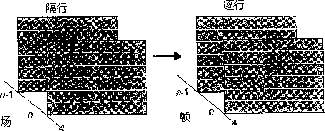
[0017] figure 1 Instructions to understand the principle of interleaving. As shown, an interlaced image sequence generates a progressive image sequence by interpolating each image field. The solid lines in the interlaced image in the figure represent the pixels of the original row, and the dotted lines represent the pixels of the row to be interpolated. These interpolated line pixels can be generated in many ways, among which motion compensation techniques are more advanced.
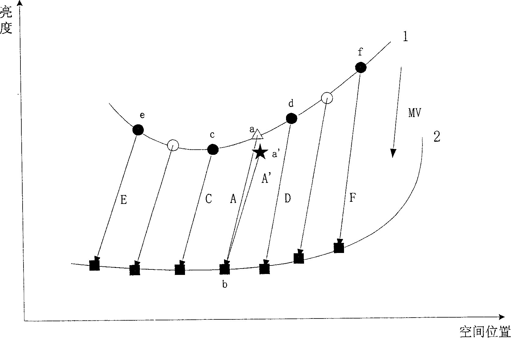
[0018] figure 2 Middle ○ indicates the pixel to be interpolated; ● indicates the original pixel of the current input field; △ indicates the pixel to be interpolated currently to be processed; ■ indicates the pixel for motion compensation. ★Indicates the pixel after correcting motion compensation. "1" indicates a spatial neighborhood of the pixel to be interpolated; "2" is a spatial neighborhood of the motion-compensated pixel matched by the motion vector of "1".
[0019] a is the actual value of th...
PUM
 Abstract
Description
Claims
Application Information