Method of making paper carrier strip

A manufacturing method and carrier tape technology, applied in the direction of container manufacturing machinery, paper/cardboard containers, containers, etc., can solve problems such as difficult to meet, deformation of side wall shape, etc.

Inactive Publication Date: 2003-10-15
TOKYO WELD CO LTD
View PDF1 Cites 3 Cited by
  • Summary
  • Abstract
  • Description
  • Claims
  • Application Information

AI Technical Summary

Problems solved by technology

Therefore, it is difficult to satisfy the above condition (ii)
In addition, when the carrier tape 1 is manufactured by direct press working on the paper carrier tape base material 1a in order to form the chip storage recess 3, as Figure 7 As shown, in the case where the chip storage recesses 3 are narrowly spaced from each other, when using press processing to open the hole chip storage recess 3, since the side wall of the previously perforated chip storage recess 3 is pressed, the previously perforated chip storage recess 3 will The shape of the side wall will be deformed, making it difficult to satisfy the above condition (i)
[0020] also, Figure 6C The shown paper carrier tape 1, since there are holes at the bottom of the chip storage recess 3, is difficult to satisfy the above condition (iii)

Method used


Image

  • Method of making paper carrier strip
  • Method of making paper carrier strip
  • Method of making paper carrier strip

Examples


Embodiment Construction

[0039] Embodiment of the invention

[0040] Hereinafter, embodiments of the present invention will be described with reference to the drawings.

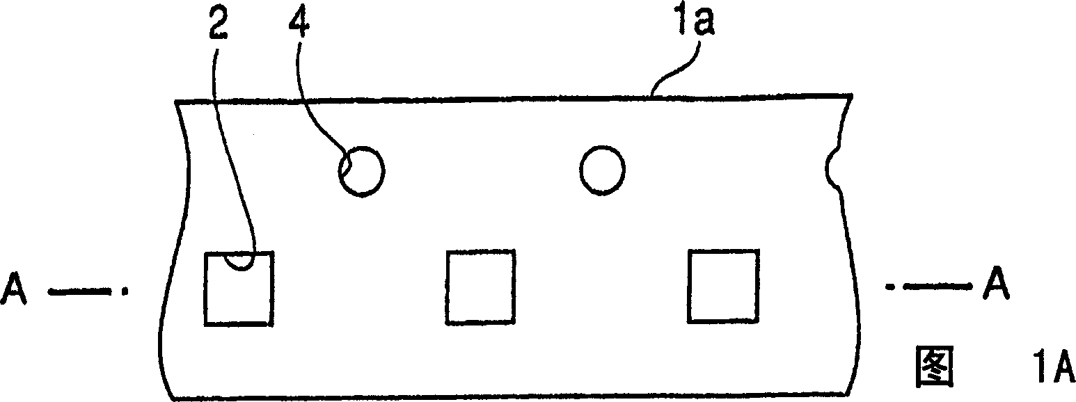
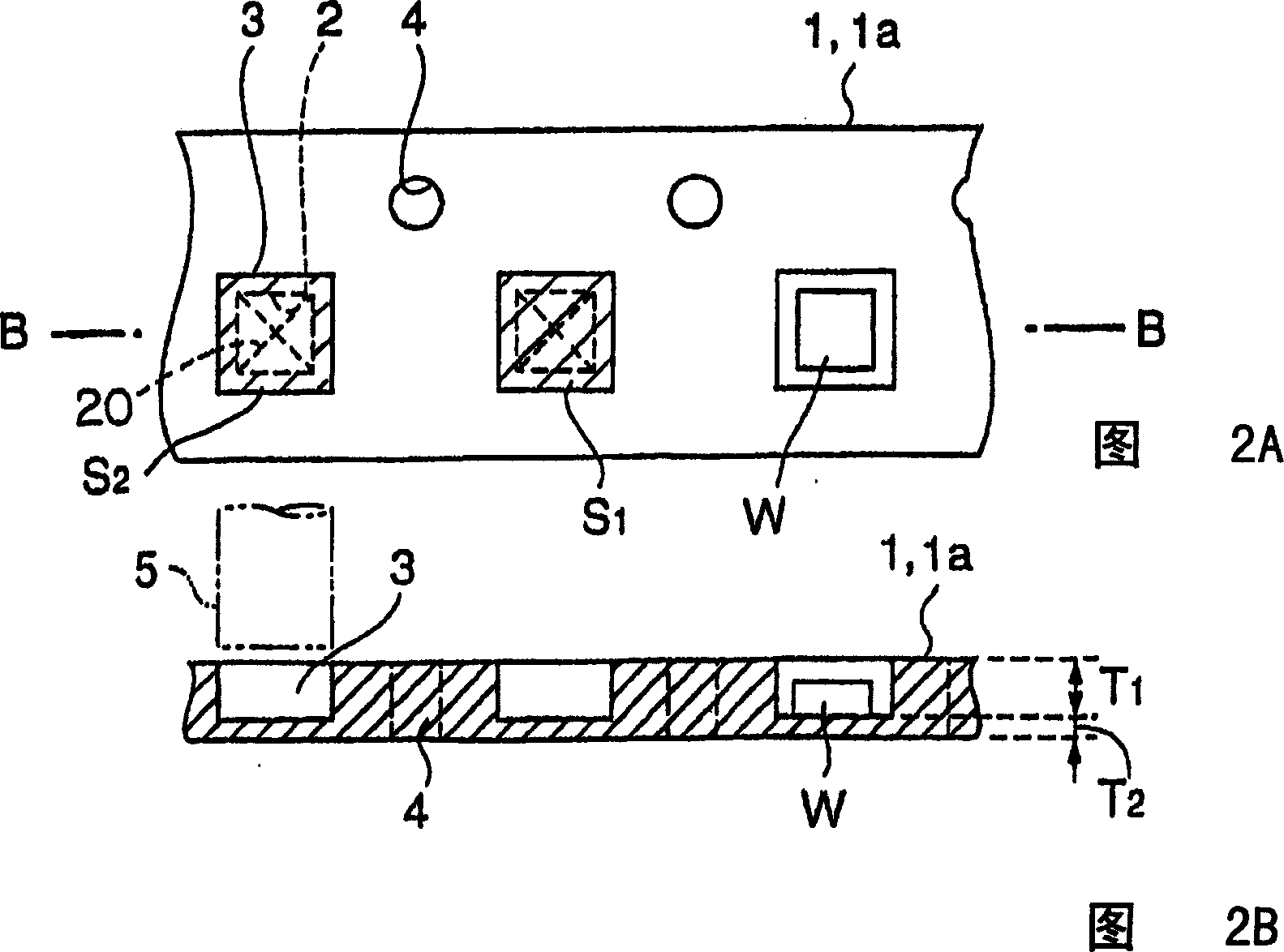
[0041] Fig. 1 and Fig. 2 are embodiment figure of the present invention. Fig. 1 is a first step diagram of a method of manufacturing a paper carrier tape. Fig. 2 is its second process drawing. Fig. 1A is a view of the paper carrier tape of the first process viewed from above, Figure 1B It is a sectional view of part A-A of Fig. 1A. Fig. 2A is a view of the paper carrier tape in the second step viewed from above, and Fig. 2B is a cross-sectional view of part B-B of Fig. 2A.

[0042] First, as shown in Figure 1A, Figure 1B As shown, the thickness of the paper carrier tape base material 1a is standardized at 0.31mm, 0.43mm, 0.61mm, 0.75mm, 0.95mm, etc. For example, a paper carrier tape base material 1a with a thickness of 0.61mm is prepared. This paper carrier tape base material 1a, in the 1st process, as shown in Figure 1A, F...


PUM


Abstract

The manufacture of carrier paper tape includes the first step of forming through hole on the paper base and the second step of pressing punching pin on the through hole to form chip storing notch in the through hole and closing the through hole with partial paper base material. The carrier paper tape thus manufactured has precise chip storing notch, which has no hole in the bottom and may be opened simply.

Description

technical field [0001] The present invention relates to a method of manufacturing a paper carrier tape for supplying chip-shaped electronic components after mounting the chip-shaped electronic components on a fixture such as a printed substrate. Background technique [0002] Conventionally, plastics and paper are known as carrier tapes for supplying chip-like electronic components after mounting the chip-like electronic components on a fixture such as a printed substrate. [0003] Figure 5A, Figure 5B It is a drawing of a manufacturing method of a plastic carrier tape disclosed in JP-A-1-314150. In Figure 5A, Figure 5B In the illustrated example, first, as shown in FIG. 5A , a through-hole 2 with an opening narrower than that of the chip storage recess 3 is opened in the plastic carrier tape base material 11 a. Another example Figure 5B As shown, the through-hole 2 is press-punched, and the chip storage recess 3 with a required depth T1 is formed on the through-hole by p...

Claims


Application Information

Patent Timeline
Patent Type & Authority Applications(China)
IPC IPC(8): B31B1/14B65D75/34
Inventor 千叶实冈村松男齐藤晃吉原孝雄
Owner TOKYO WELD CO LTD
Why Eureka
Try Eureka