Refrigerating apparatus and an inverter device used therein

A refrigeration device and inverter technology, applied in refrigeration and liquefaction, output power conversion devices, irreversible cycle compressors, etc., can solve the problems of not considering the refrigeration cycle, not fully considering the refrigeration device, etc.

Inactive Publication Date: 2003-10-15
JOHNSON CONTROLS HITACHI AIR CONDITIONING
View PDF0 Cites 15 Cited by
  • Summary
  • Abstract
  • Description
  • Claims
  • Application Information

AI Technical Summary

Problems solved by technology

[0003] In the prior art described above, the degree of freedom for specification changes is increased, but since the problem of use in the refrigeration circuit is not considered in particular, in the refrigeration circuit, the detection sensors for various degrees of warmth or pressure of the refrigeration circuit are used After the signal is taken into the microcomputer, the unique problem of inverter control suitable for the refrigeration cycle is not considered, and the unique problem of requiring miniaturization of the refrigeration device itself is not fully considered.

Method used


Image

  • Refrigerating apparatus and an inverter device used therein
  • Refrigerating apparatus and an inverter device used therein
  • Refrigerating apparatus and an inverter device used therein

Examples


Embodiment Construction

[0018] Hereinafter, an embodiment of the present invention will be described with reference to the drawings.

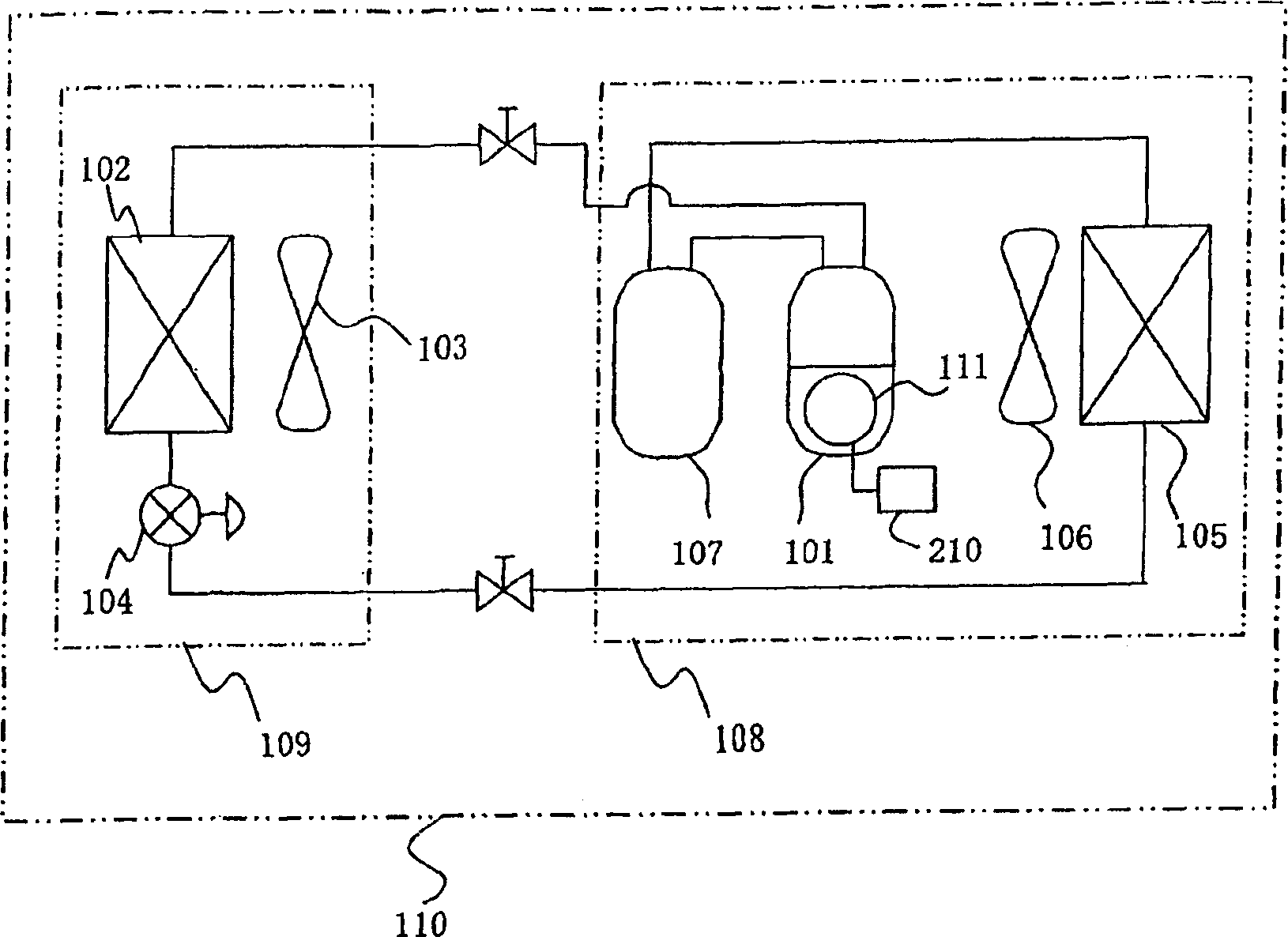
[0019] figure 1 It is a refrigerating cycle system diagram of an embodiment, in which a compressor 101, an indoor heat exchanger 102, an indoor expansion valve 104, an outdoor heat exchanger 105, and a storage battery 107 are sequentially connected to circulate the refrigerant to form a refrigerating cycle. Moreover, in the case of cooling the room, the refrigerant compressed by the compressor 101 is condensed and liquefied in the outdoor heat exchanger 105, decompressed in the indoor expansion valve 104, evaporated in the indoor heat exchanger 102, and returned to the Compressor 101. The motor 103 for the indoor blower promotes heat exchange with the indoor unit 109 , and the motor for the outdoor blower promotes heat exchange with the outdoor unit 108 .

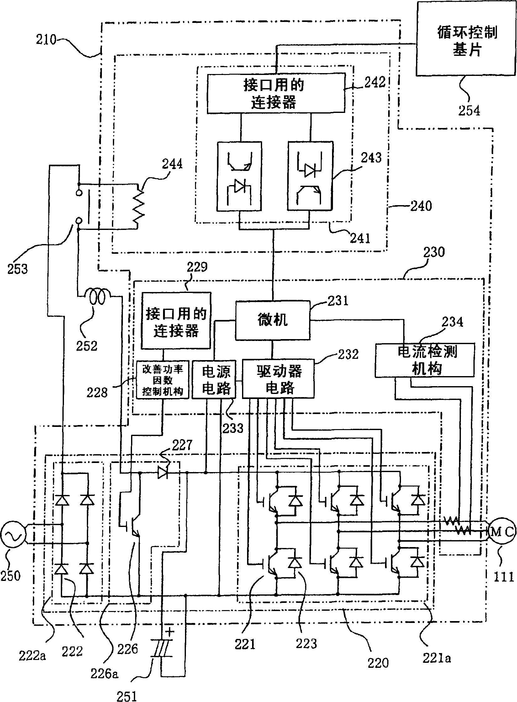
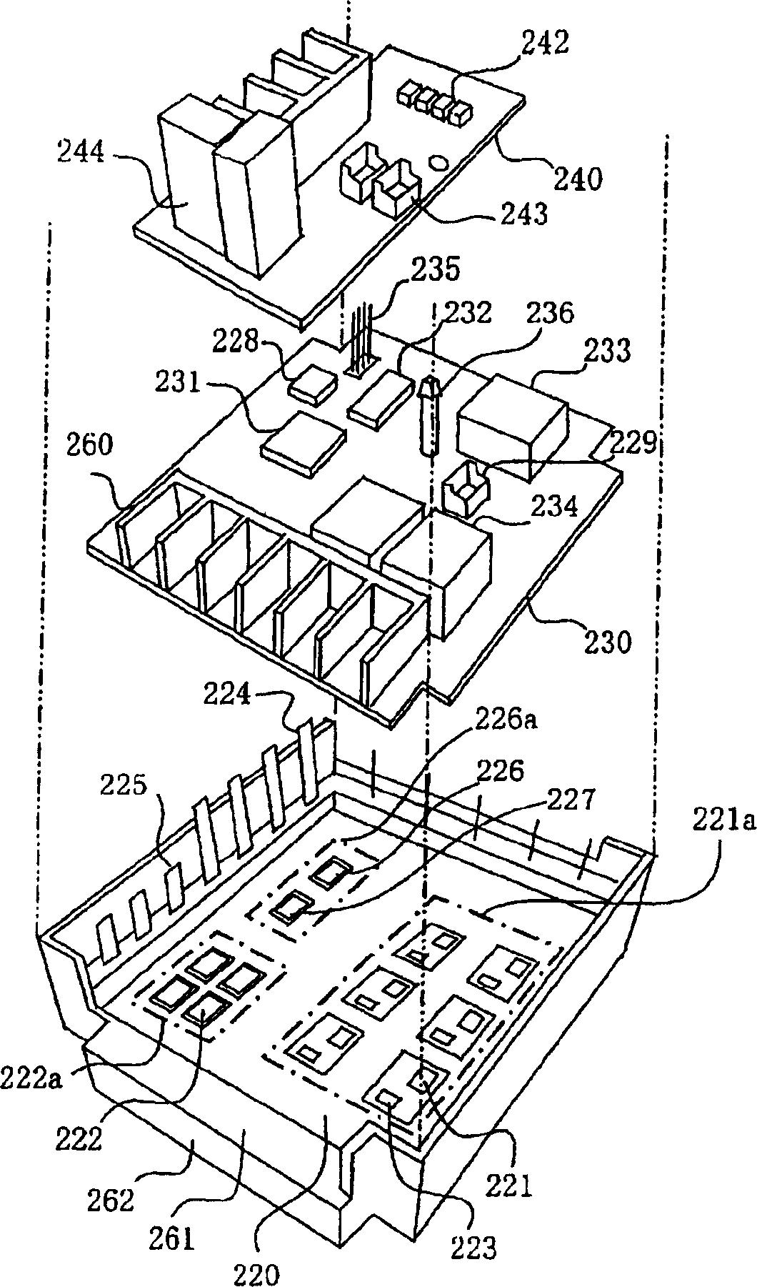
[0020] The compressor 101 is associated with the capacity required by the refrigerating circuit, and is driven...


PUM


Abstract

A refrigerating apparatus comprises: a first substrate, on one surface of which an active converter and an inverter are mounted, and on a reverse surface of which a radiation fin is closely fixed; a second substrate, on which a microcomputer, a current detecting mechanism, and a terminal block are mounted; a resin casing covering sides of the first and second substrates and provided with a step permitting the terminal block to be arranged thereon; and a third substrate, on which an interface connector and a photo-coupler are mounted. The first substrate, the second substrate, and the third substrate are layered in this order on a bottom surface of the casing. Gel is filled up to a power semiconductor surface of the first substrate, and a resin is filled up to an upper surface of the second substrate.

Description

technical field [0001] The present invention relates to a refrigeration device equipped with a compressor motor with a variable number of revolutions and an inverter device used in the device. Background technique [0002] It is known that in the past, in order to facilitate the specification change without changing the basic part of the inverter, it is divided into inverters that convert AC voltage from AC power sources into DC and inverters that are DC / AC converters. The basic part of the inverter consisting of the first substrate, the controller including the microcomputer that controls the inverter, the second substrate, and the third substrate on which the terminal board, surge suppression resistor, and smoothing capacitor are mounted, And the I / O block portion that manages the input / output interface in the microcomputer process that manages the inverter control device is described in, for example, JP-A-11-41943. [0003] In the prior art described above, the degree of...

Claims


Application Information

Patent Timeline
Patent Type & Authority Applications(China)
IPC IPC(8): F25B49/02H02M1/00H02M1/42H02M7/00
CPCH02M7/003F25B49/025H02M2001/007Y02B30/741Y02B70/126H02M1/4225F25B2600/021F25B2700/151Y02B30/70Y02B70/10H02M1/007H02M7/48F25B1/00
Inventor 栗田佳明高塚邦明安藤达夫山田憲昭古泽智
Owner JOHNSON CONTROLS HITACHI AIR CONDITIONING
Why Eureka
Try Eureka