
Routing device and method in network

A technology for selecting devices and relaying devices, which is applied in the fields of selecting devices, data exchange networks, digital transmission systems, etc., and can solve the problems of difficulty in implementation, high LSR cost, lack of freedom and flexibility, etc.

Inactive Publication Date: 2003-10-29
FUJITSU LTD
View PDF0 Cites 1 Cited by
  • Summary
  • Abstract
  • Description
  • Claims
  • Application Information

AI Technical Summary

Problems solved by technology

For this reason, for example, even if a network administrator tries to provide individual services on the network, implementation is difficult due to lack of freedom and flexibility
[0017] In addition, since it is necessary to provide all capabilities (hardware and software) sufficient to realize the above functions 1) to 4), there is a problem that LSR becomes high in cost

Method used


Image

  • Routing device and method in network
  • Routing device and method in network
  • Routing device and method in network

Examples


Embodiment Construction

[0038] Preferred embodiments of the present invention will be described in detail below with reference to the accompanying drawings.

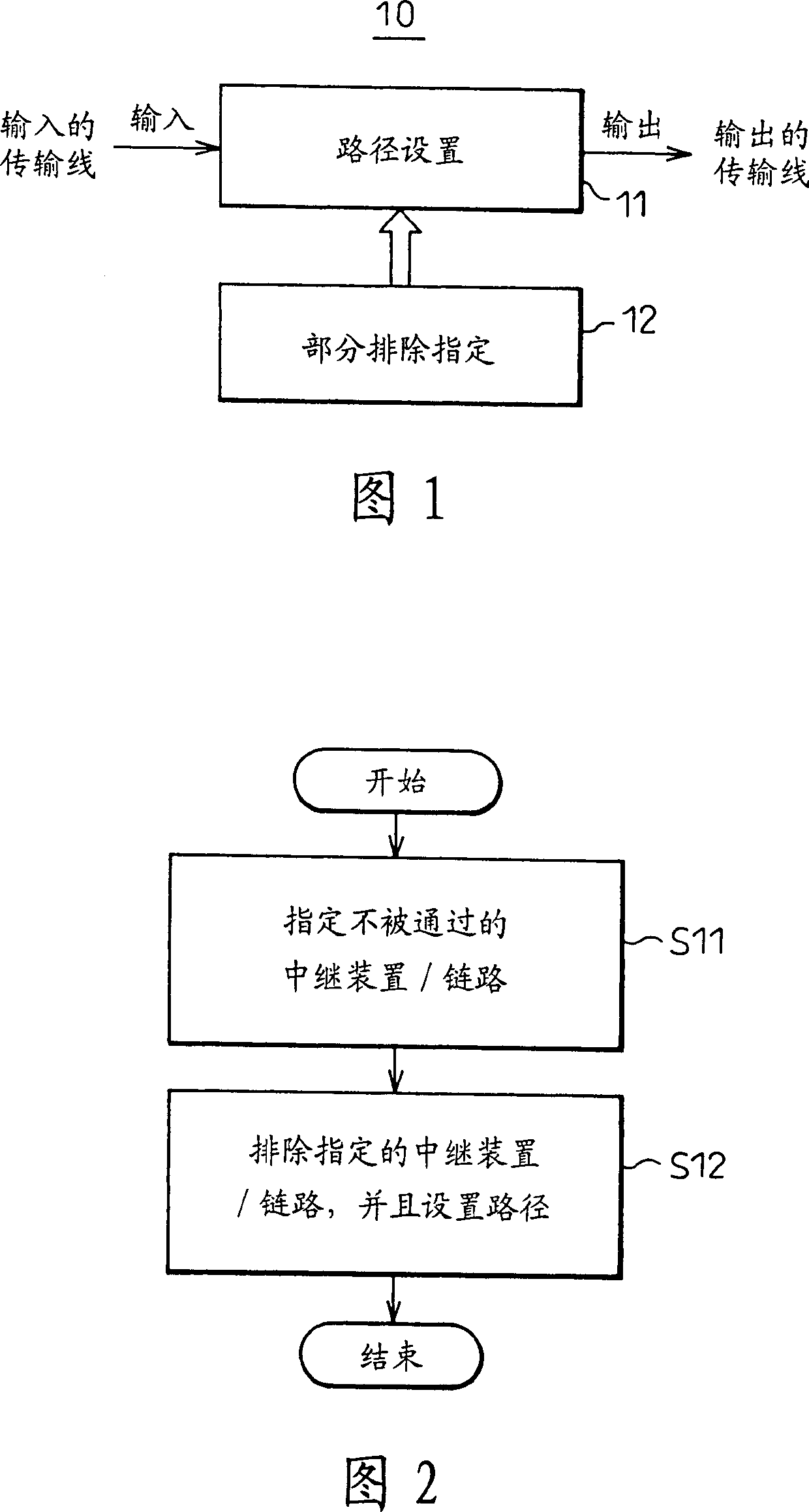
[0039] Fig. 1 is a basic structural view of a routing device according to the present invention;

[0040] In the figure, reference numeral 10 denotes a routing device in a network supporting label switching among a plurality of relay devices. The routing means 10 has at least a path setting means 11 and a partial exclusion specifying means 12 . Here, path setting means 11 sets a path to be label-switched in the network, while partial exclusion specifying means 12 specifies to the path setting means 11 one or more parts not to pass in the path to be set.

[0041] Here, "part" means at least one of a part where one relay device is located or a part where a link spanning a plurality of relay devices is located.

[0042] In addition, a "relay device" is a node or an interface configuring the network.

[0043] The present invention can also be un...


PUM


Abstract

A routing device in a network supporting label switching among a plurality of relay devices, comprising a path setting unit for setting a path to be label switched in the network and a path setting unit for specifying to the path setting unit Partial exclusion of one or more sections that do not pass among the paths to be set specifies the unit. Thus, the degree of freedom and flexibility of route selection can be improved.

Description

field of invention [0001] The present invention relates to a routing device and a routing method in a network, in particular to an intra-enterprise local area network, an Internet backbone network, an optical network, and a transmission network using multi-protocol label switching and / or general multi-protocol label switching (MPLS / GMPLS). A constraint-based routing technique or an explicit routing technique in et al. Background technique [0002] "Label Switching" is a basic technology used to realize really high-speed data transmission, traffic distribution, bandwidth control, etc. for intra-corporate LANs and Internet backbone networks. It combines routing at an IP level (Layer 3) with switching at an ATM, Frame Relay, Ethernet, or other lower layer (Layer 2), giving an IP packet a "label", and Layer 2 forwarding is performed through this "label". This label switching is currently standardized as MPLS in the MPLS-WG (Working Group) of the Internet Engineering Task Force...

Claims


Application Information

Patent Timeline
IPC IPC(8): H04L45/50
CPCH04L45/10H04L45/50
Inventor 笹川靖
Owner FUJITSU LTD
Learn More