Eureka AIR delivers breakthrough ideas for toughest innovation challenges, trusted by R&D personnel around the world.

Fuel conveying pipe

A technology of fuel delivery and fuel, which is applied in fuel injection devices, low-pressure fuel injection, charging systems, etc., and can solve the problems that noise cannot be transmitted, spread, and radiated

Inactive Publication Date: 2003-11-05
USUI KOKUSAI SANGYO KAISHA LTD
View PDF4 Cites 1 Cited by
  • Summary
  • Abstract
  • Description
  • Claims
  • Application Information

AI Technical Summary

Problems solved by technology

[0005] But like Figure 10A As shown, when the top surface 85 of the communication pipe is located on the absorption surface, there is a problem that a standing wave is generated near the fuel inlet 13, and the fuel delivery pipe mechanically resonates with the standing wave. Yes, the noise in the high-frequency region cannot be transmitted, propagated, and radiated to the surroundings of the fuel delivery pipe

Method used


Image

  • Fuel conveying pipe
  • Fuel conveying pipe
  • Fuel conveying pipe

Examples


Embodiment

[0069] A test for confirming the effect of the present invention was conducted using an actual engine.

[0070] (1) Fuel delivery pipe: the width is 34mm, the height is 10.2mm, the length is 300mm, the plate thickness is 1.2mm, STKM11A steel pipe;

[0071] (2) Fuel pipe: outer diameter 8mm, thickness 0.7mm, STKM11A steel pipe

[0072] (3) Engine: relative type 6 cylinders;

[0073] (4) Measuring part: On the longer fuel pipe on the floor of the automobile, an acceleration sensor is installed near the connection part of the nylon pipe connected to the fuel inlet pipe 5 on the side of the fuel delivery pipe to measure changes in acceleration.

[0074] As a result of measurement by a standard type not using the clip of the present invention, it can be known that the peak frequency components where pulsating noise is likely to occur are located in the vicinity of 600 Hz and 1.3 kHz. As a result of measuring by installing one clip of the present invention at one place in the cent...


PUM


Abstract

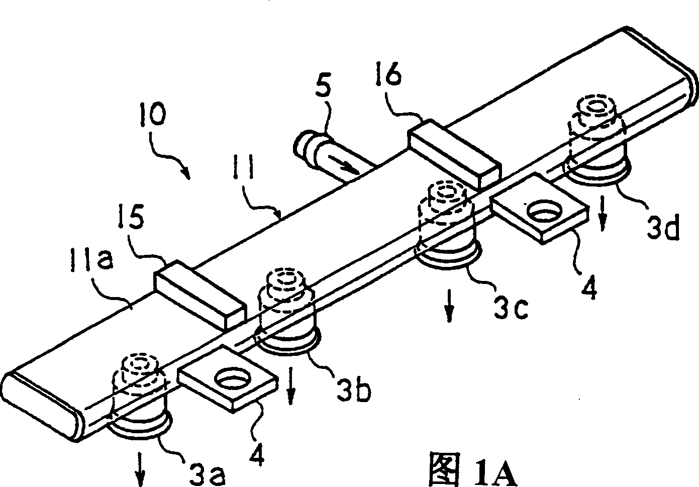
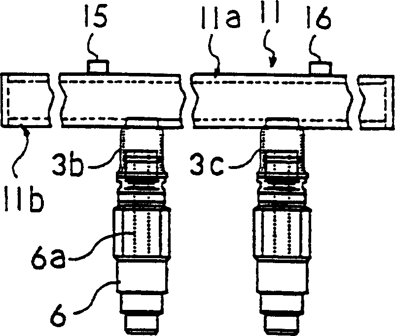
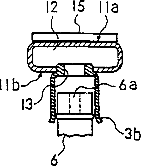
The present invention provides a fuel delivery pipe for an electronic fuel injection type automobile engine, which can reduce the shock wave and pulsating pressure generated with the opening and closing of the fuel nozzle, and can reduce the occurrence, transmission, and propagation of noise in the high-frequency region ,radiation. A flexible absorbing surface is formed in a flat or arcuate shape on the outer wall of the communicating pipe, and ribs intersecting the axial direction of the communicating pipe are fixed to the outside of the absorbing surface, or recesses are formed on the absorbing surface. Or, install a clamping member that clamps the connection installation surface and the absorption surface of the connecting pipe from both sides. The position of the above-mentioned rib or clip is preferably in the vicinity of the end of the communication pipe in the axial direction. As a result, the noise in the high-frequency region radiated from the fuel delivery pipe is reduced, and the pulsating pressure and shock waves of the fuel flowing into the connection are reduced by deflection of the absorbing surface.

Description

technical field [0001] The present invention relates to an improvement of a fuel delivery pipe, which is used to supply fuel from an electronic fuel injection type automobile engine through a fuel injector (nozzle) that directly injects directly into each intake passage of the engine or inside a cylinder. The fuel provided by the fuel booster pump, the present invention particularly relates to the cross-sectional structure of the communication pipe with the fuel passage and the external structure of the communication pipe. Background technique [0002] The fuel delivery pipe is widely used in the electronic fuel injection system of gasoline engines, which includes a communication pipe with a fuel passage, through a plurality of cylindrical ports, to send fuel to the fuel injector, and then return it to the fuel tank side for use The type of the return path of the return path, and the type that does not have a return path (non-return). Recently, in order to reduce the boil-o...

Claims


Application Information

Patent Timeline
Patent Type & Authority Applications(China)
IPC IPC(8): F02M55/02F02M55/04
CPCF02M55/025F02M55/04F02M69/465F02M55/02
Inventor 土屋光芹泽由之小方哲夫水野贺寿光
Owner USUI KOKUSAI SANGYO KAISHA LTD
Why Eureka
Eureka Blog
Learn More