Projection optical system, exposure apparatus with the same system and exposure method

A projection optical system and image projection technology, applied in the field of exposure devices, can solve the problems of deterioration of imaging performance and the like

Inactive Publication Date: 2003-11-05
NIKON CORP
View PDF4 Cites 42 Cited by
  • Summary
  • Abstract
  • Description
  • Claims
  • Application Information

AI Technical Summary

Problems solved by technology

At this time, in the projection optical system, due to the large NA (value aperture), a certain degree of oblique light will also pass through the lens from the crystal axis [111], so the imaging performance may be deteriorated due to the influence of birefringence

Method used


Image

  • Projection optical system, exposure apparatus with the same system and exposure method
  • Projection optical system, exposure apparatus with the same system and exposure method
  • Projection optical system, exposure apparatus with the same system and exposure method

Examples


Embodiment Construction

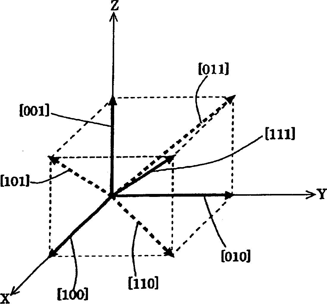
[0054] figure 1 It is an explanatory diagram of the orientation of the fluorite crystallization axis. If reference figure 1 , the crystal axis of fluorite is specified according to the XYZ coordinates of the cubic crystal system. That is, it is respectively stipulated that the crystal axis [100] is along the +X axis, the crystal axis [010] is along the +Y axis, and the crystal axis [001] is along the +Z axis.

[0055] In addition, it is respectively stipulated that: on the XZ plane, the crystal axis [101] is in the direction of 45 degrees between the crystal axis [100] and the crystal axis [001]; on the XY plane, the crystal axis [110] is in the direction of the crystal axis [100] and The crystal axis [010] is in the direction of 45 degrees, and on the YZ plane, the crystal axis [011] is in the direction of the crystal axis [010] and the crystal axis [001] in the direction of 45 degrees. Furthermore, it is specified that the crystal axes [111] are in directions forming equa...


PUM

PropertyMeasurementUnit
thicknessaaaaaaaaaa
birefringenceaaaaaaaaaa

Abstract

A projection optical system and an exposure device of the projection optical system, in the projection optical system including a plurality of transmission members, and projecting an image on a first surface onto a second surface, including a crystal transmission member made of a crystal material, when When the effective diameter of the crystal transmission member is ED and the outer diameter of the crystal transmission member is LD, at least one of the crystal transmission members satisfies the following relationship: 0.3<ED / LD<0.95. Although an optical material with inherent birefringence such as fluorite is used, it is virtually unaffected by birefringence and ensures good optical properties.

Description

technical field [0001] The present invention relates to an exposure apparatus provided with a projection optical system and the projection optical system, and particularly relates to a projection optical system suitable for use in an exposure apparatus when microdevices such as semiconductor elements are manufactured in a photolithography process. Background technique [0002] In recent years, in the process of manufacturing semiconductor elements and manufacturing semiconductor chip packaging substrates, miniaturization has been increasing, and projection optical systems with higher resolution are required for exposure devices that transfer patterns. In order to meet this high-definition image requirement, it is necessary to increase the NA (numerical aperture of the projection optical system) while shortening the exposure light. However, if the exposure light is shortened, the types of durable optical glass are limited due to light absorption. [0003] For example, light ...

Claims


Application Information

Patent Timeline
Patent Type & Authority Applications(China)
IPC IPC(8): G02B13/18G02B1/02G02B13/24G02B17/08G03F7/20H01L21/027
CPCG02B1/02G02B17/08G02B17/0892G03F7/70225G03F7/70958G03F7/70966H01L21/027
Inventor 大村泰弘
Owner NIKON CORP
Why Eureka
Try Eureka