Oil box of sewing machine

A technology for sewing machines and oil tanks, which is applied in the direction of sewing machine components, sewing equipment, engine lubrication, etc., and can solve problems such as rising manufacturing costs and complex configurations

Inactive Publication Date: 2003-11-19
BROTHER KOGYO KK
View PDF0 Cites 9 Cited by
  • Summary
  • Abstract
  • Description
  • Claims
  • Application Information

AI Technical Summary

Problems solved by technology

However, in this case, there is a problem that the config...

Method used


Image

  • Oil box of sewing machine
  • Oil box of sewing machine
  • Oil box of sewing machine

Examples


Embodiment Construction

[0019] In order to explain this invention in detail, it demonstrates based on drawing. Figure 1 to Figure 6 An example in which the present invention is applied to an industrial sewing machine is shown.

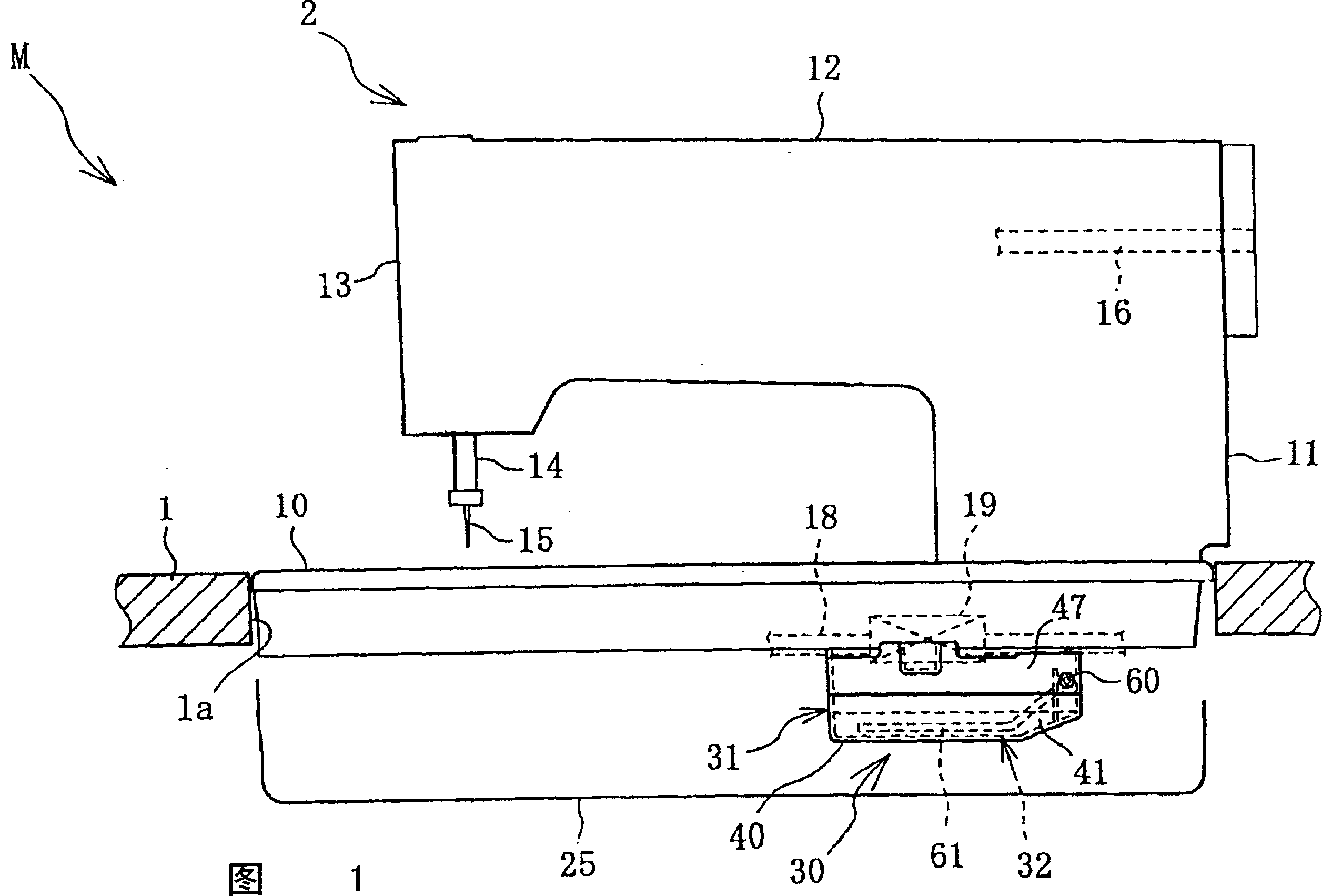
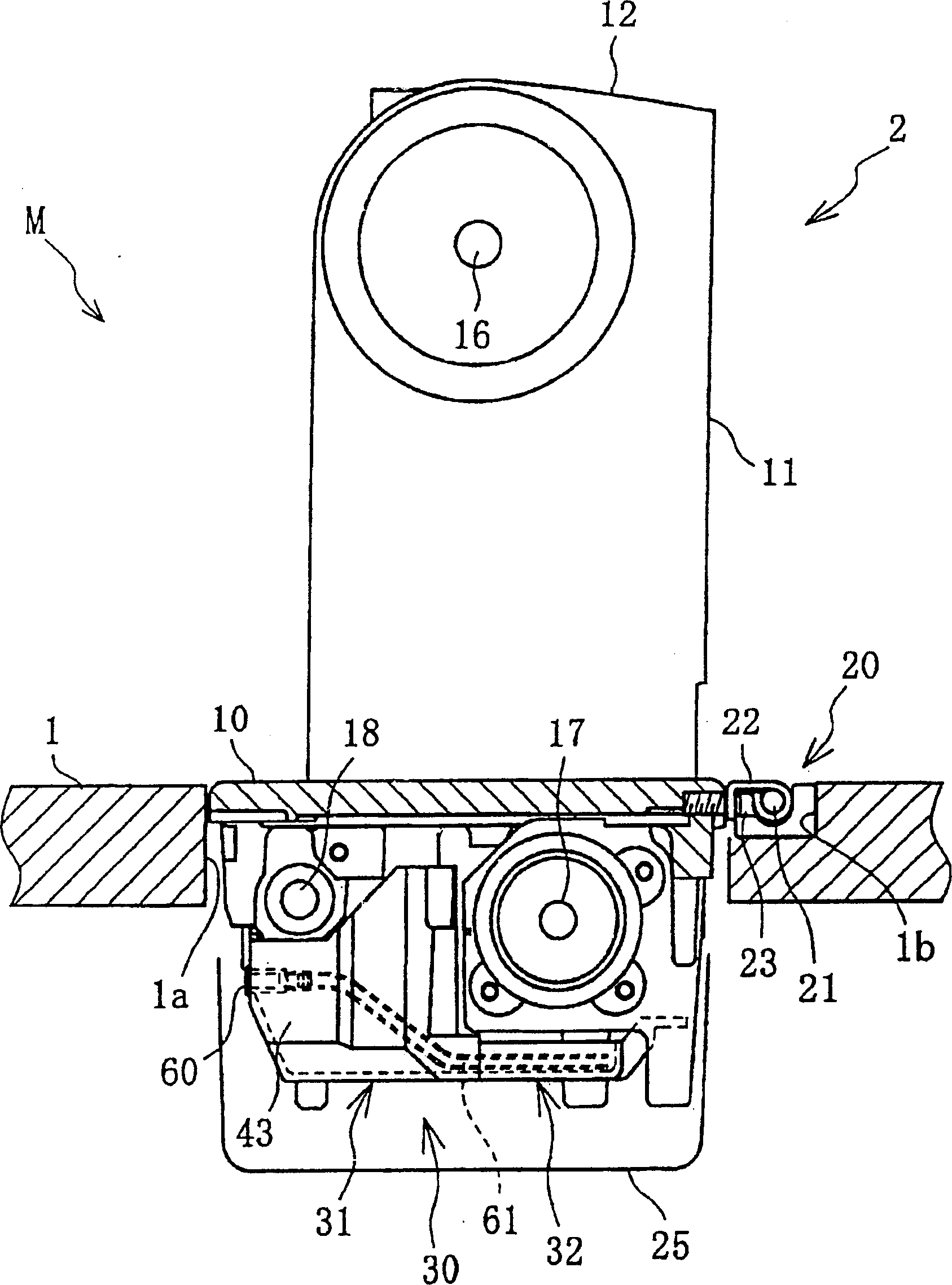
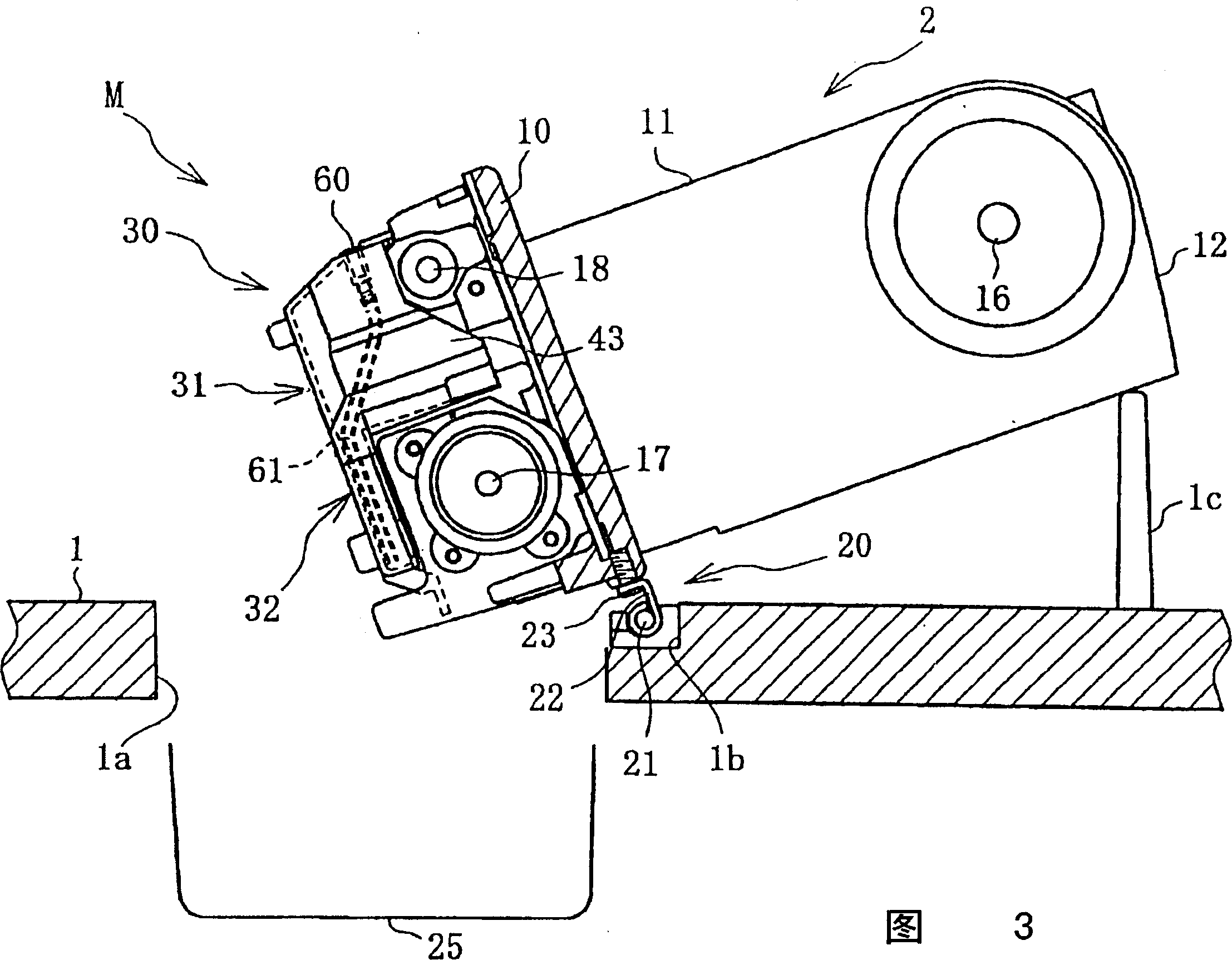
[0020] Figure 1~ Figure 4 As shown, the sewing machine of this embodiment has a sewing machine table 1, and a sewing machine main body 2 fitted into a rectangular hole 1a of the sewing machine table 1.

[0021] The sewing machine main body 2 has: a bottom plate portion 10 long in the left-right direction, a column portion 11 extending upward from the right portion of the bottom plate portion 10, and an arm portion 12 extending leftward from the column portion 11 facing the bottom plate portion 10. .

[0022] A needle bar 14 is vertically movably supported on a head 13 at the left end of the arm 12 . The lower portion of the above-mentioned needle bar 14 protrudes below the head portion 13, and a sewing needle 15 is mounted on the lower end thereof. The arm 12 is provid...


PUM


Abstract

The invention relates to an oil tank mounted on the sewing machine which has a sewing machine body for revolving by the center of horizontal axis shifted to the tilted position from the erected position, and includes an oil receiver mounted on the sewing machine body for storing the oil for lubrication and an oil container mounted on the oil receiver which can house all of the oil stored in the oil receiver when the sewing machine body is shifted to the tilted position from the erected position.

Description

【Technical field】 [0001] The present invention relates to an oil tank of a sewing machine, in particular to an oil tank with an oil container fixed on a sewing machine body and an oil reservoir capable of containing all the oil stored in the oil container when the sewing machine body is converted to an inclined position. 【Background technique】 [0002] In a conventional sewing machine, an oil pan is disposed below a mechanism such as a feed adjustment mechanism provided on a sewing machine main body. Furthermore, the lubricating oil supplied to the above-mentioned mechanism part, especially the oil dropped from the above-mentioned mechanism part at the time of the oil wick oiling, is caught by the above-mentioned oil receiver. [0003] When the above-mentioned oil container is composed of only a box-shaped member with an open upper end, it may be composed of the above-mentioned box-shaped member and an oil reservoir provided at the bottom thereof. On the other hand, in the ...

Claims


Application Information

Patent Timeline
IPC IPC(8): D05B71/00F16N19/00
Inventor 岩越弘恭水谷智晴大利人美池田尚文
Owner BROTHER KOGYO KK
Why Eureka
Try Eureka