Method for producing ball valve body

A manufacturing method and technology for spherical valve bodies, which are applied to valve devices, cocks including cut-off devices, engine components, etc., can solve problems such as the inability to manufacture ball valve bodies by continuous molding, and the difficulty in effectively improving the production efficiency of ball valve bodies.

Inactive Publication Date: 2003-11-26
邱张素月
View PDF0 Cites 3 Cited by
  • Summary
  • Abstract
  • Description
  • Claims
  • Application Information

AI Technical Summary

Problems solved by technology

Its main disadvantage is that each stamping can only form one spherical valve body blank, and it is a batch production method, which cannot

Method used


Image

  • Method for producing ball valve body
  • Method for producing ball valve body
  • Method for producing ball valve body

Examples


Embodiment Construction

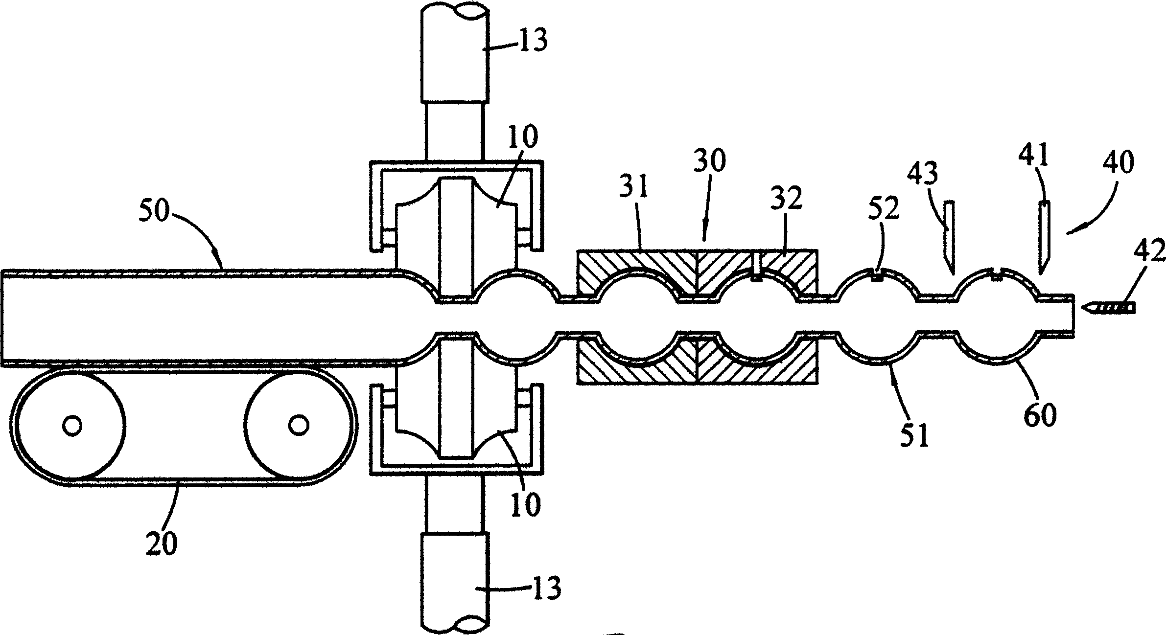
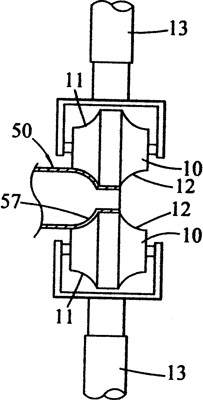
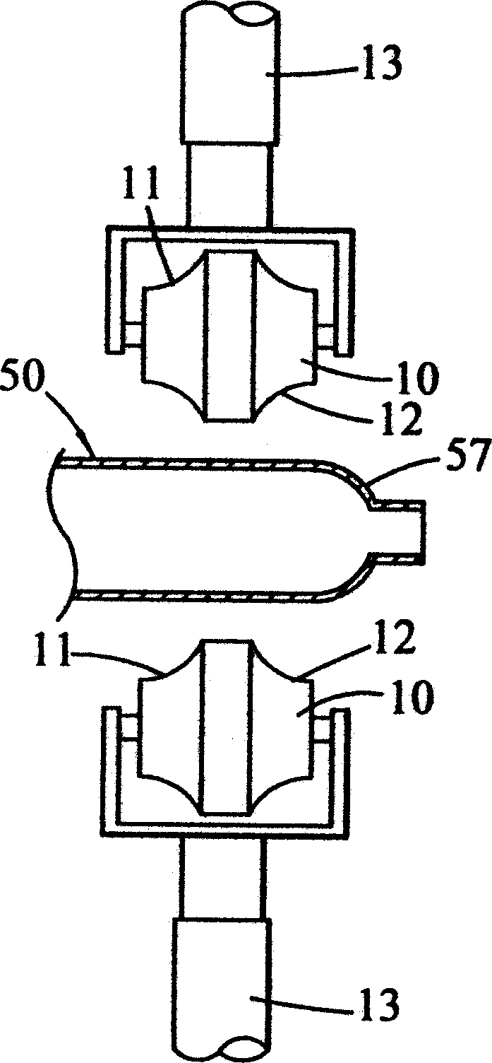
[0017] Please refer to the figures at the same time. The manufacturing method of the ball valve body provided by the present invention mainly includes the following steps: a) Using a roll forming process, a long metal tubular material 50 is rolled into a continuous series of string ball valves body blank 51; b) forming at least one valve stem fixing groove 52 separately or simultaneously on the string-type spherical valve body blank 51 by stamping or milling; c) cutting the string-type spherical valve body blank 51 into There are spherical valve body monomers with openings 53 and 54 at both ends; and d) turning each spherical valve body monomer to correct the roundness and surface polishing treatment, so as to make it as Figure 6 The spherical valve body 56 configuration is shown.

[0018] This long tubular material 50 for preparing the string type spherical valve body blank 51 is to use suitable metal materials such as stainless steel tubes, copper pipes, and its caliber is ...


PUM


Abstract

The production process of ball valve body is one rolling formation process. Tubular metal material is first rolled into one string of ball valve body blanks, the ball valve body blanks are then punched or milled to form valve rod fixing groove, surface turned and ground to correct degree of sphericity, and the string of ball valve body blanks is finally cut into ball valve bodies with opened ends.

Description

technical field [0001] The invention relates to a manufacturing method of a ball valve body, in particular to a method of continuously forming a series ball valve body from a metal tubular material by means of rolling processing, and then cutting and post-processing into a ball valve body. method. Background technique [0002] The spherical valve body of the ball valve is traditionally formed by casting, which has the problem of sand holes in the casting. Therefore, the diameter of the casting spherical valve body blank is usually more than 1.5 times the diameter of the finished product, and the blank is turned to the required size of the finished product. diameter, which is not only cumbersome and time-consuming in manufacturing and processing, but also cannot completely solve the problem of sand holes on castings, resulting in a product defect rate of up to 30% to 50%, which seriously affects the processing speed of manufacturing spherical valve bodies, material waste and ...

Claims


Application Information

Patent Timeline
IPC IPC(8): B23P13/00F16K5/06
Inventor 邱张素月
Owner 邱张素月
Why Eureka
Try Eureka