Structure of LED base and pins and producing method

A manufacturing method and pin technology, applied in electrical components, electrical solid devices, circuits, etc., can solve the problems of narrowing pin spacing, increased drilling, uneven thickness, etc.

Inactive Publication Date: 2003-11-26
张修恒
View PDF0 Cites 4 Cited by
  • Summary
  • Abstract
  • Description
  • Claims
  • Application Information

AI Technical Summary

Problems solved by technology

But the LED grain of this kind of device can not use the known three-pin packaging structure, changing to four pins will make the width wider, which is not conducive to miniaturizatio

Method used


Image

  • Structure of LED base and pins and producing method
  • Structure of LED base and pins and producing method
  • Structure of LED base and pins and producing method

Examples


Embodiment Construction

[0036] The content of the present invention can be illustrated through the following embodiments with the accompanying drawings. Although the structure and manufacturing method of the structure base and pins of the present invention take the package of four pins as an example. However, three or more pins can also be implemented utilizing the principles of the present invention.

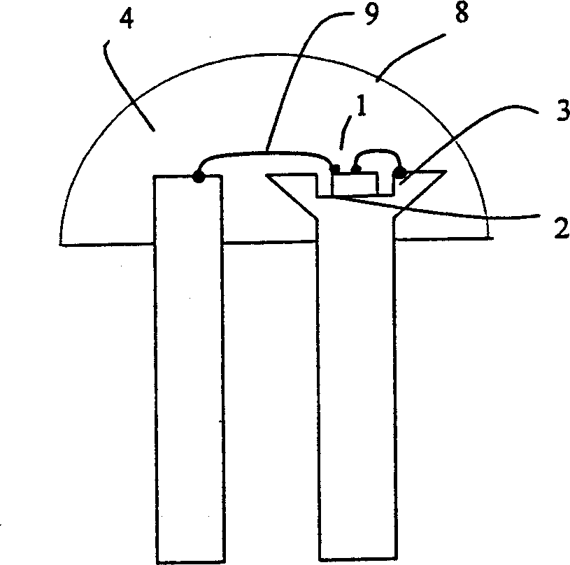
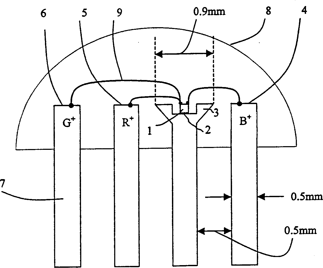
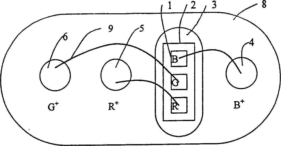
[0037] According to the first embodiment of the present invention, refer to Figure 5 , which is a plan view of the structure of the four pins and the base of the three-primary-color LED. One end of the first pin 51 forms the base and the shared negative terminal block 3, and a groove forms a die seat 2 for stacking the three-primary-color LED dies for installation. The grain seat 2 is a groove with a circular parabolic side wall, which focuses the reflected light and then shines forward to increase the brightness. One end of the second, third, and fourth pins 52, 53, and 54 form blue, red, and gree...


PUM


Abstract

This invention illustrates structure of three primary colors LED four plug pins and packaged base and its manufacturing method, among which one of the pins forms a grain base and a share negative connector base, the other three form positive connector base. The connector baser are placed at four corners of a square, two extend to the right, the other two to the left and they are formed by punch die, etching or coating. Multiple boses are formed in one run, then four pins are bent down by 90 deg. in one same direction from near the connector base to a standing state to be processed with grain welding and lining at first, then to be cut into a single structure and sealed with transparent plastic by moulding.

Description

technical field [0001] The present invention relates to LED structures, in particular to the structure of the base and pins of the three-primary-color LED structures and its manufacturing method. Background technique [0002] Generally, a single-color light-emitting diode (LED) is constructed with two pins, while a two-complementary color LED is constructed with three pins, and a three-primary color (red, blue, green) LED is constructed with three or four pins. prongs. figure 1 It is a cross-sectional view of a conventional single-color LED with two pins. Negative terminal block 3 has a groove for die block 2, die 1 is welded on die block 2 by die bond, and then the positive and negative electrodes are respectively connected to the positive electrode with gold wire or aluminum wire 9 The terminal block 4 and the negative electrode terminal block 3 are then sealed with a transparent plastic 8 to form a ring-shaped focusing lens. figure 2 It is a cross-sectional view of th...

Claims


Application Information

Patent Timeline
IPC IPC(8): H01L25/075H01L33/00
CPCH01L2224/48257H01L2224/48091H01L2224/48247H01L2224/45124H01L2224/45144
Inventor 张修恒
Owner 张修恒
Why Eureka
Try Eureka