
Electric permanent magnet motor

A kind of engine, DC motor technology, applied in the direction of generator/motor, electrical components, electromechanical devices, etc., can solve the problems of uncontrolled repulsion and attractive force, increased self-loss, increased output power, etc., to achieve small size, No exhaust emission, low power effect

Inactive Publication Date: 2003-11-26
陈福才 +1
View PDF5 Cites 0 Cited by
  • Summary
  • Abstract
  • Description
  • Claims
  • Application Information

AI Technical Summary

Problems solved by technology

[0002] The engine is one of the indispensable machines in machinery, metallurgy, chemical industry, transportation and other industries. The energy used by the existing engines is mostly coal, oil, electricity and other non-renewable resources as power energy. The above-mentioned energy pollutes the environment and is harmful human health
In recent years, people have made great efforts in the utilization and development of wind energy, water energy and solar energy. The above-mentioned energy sources have the characteristics of not polluting the environment and having a wide range of energy sources, but they are affected by geographical conditions and climate, and their application costs are relatively high. Difficult to promote the application
Permanent magnet technology has been greatly developed in recent years, especially in generators and motors. However, with the increase of working time and output power, its own loss increases accordingly, and the repulsion force and attraction without means of control

Method used


Image

  • Electric permanent magnet motor
  • Electric permanent magnet motor
  • Electric permanent magnet motor

Examples


Embodiment

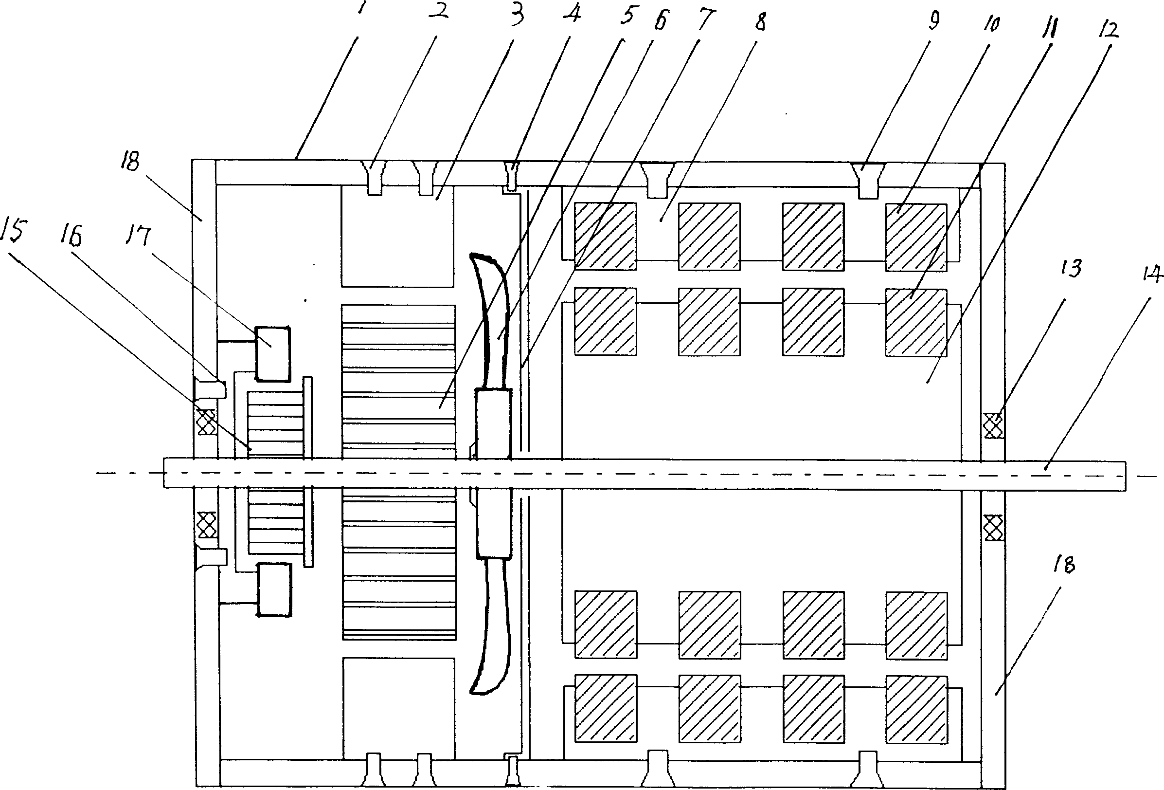
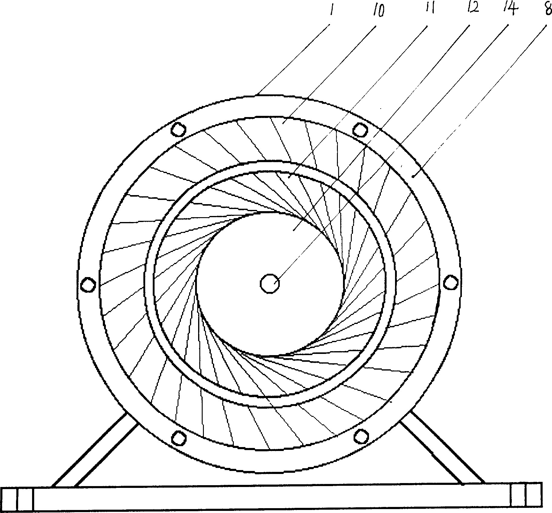
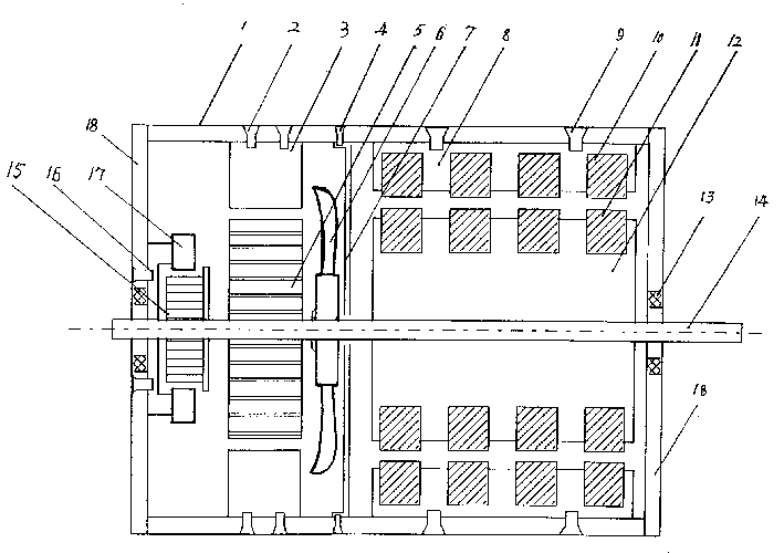
[0008] The manufacturing process of the present invention is the same as that of the existing engine, and can be manufactured by general machinery factories, especially electric motor factories. The design basis of the permanent magnet motor is the principle that the same-sex magnetic poles repel each other and the opposite-sex magnetic poles attract each other. After the DC motor is powered on, the DC motor rotor 5 rotates, driving the output shaft 14 to rotate, and the permanent magnet motor rotor 12 coaxial with the output shaft 14 rotates, and the rotor permanent magnet 11 on the rotor 12 is subjected to permanent magnet during rotation. The repulsive force of the stator permanent magnets 10 on the stator 8 of the engine produces a repulsive thrust acting on the side of the rotor, which is decomposed into component forces along the tangential direction of the rotor circumference, and generates a rotational moment to make the rotor rotate an angle, and the repulsive force fo...


PUM


Abstract

This invention relates to an eelctric permanent magnetic engine including a shell, a DC generator, a commutator, a fan, stators, rotors, a bearing, an output shaft, a shielding partition, among whichthe output shaft is mounted on the rotors of the motor and the permanent magnetic engine with shielding partition in-between. Stators of DC motor and the magnetic engine are fixed in the case corresponding to the rotors, the permanent magnets of the stator and rotor are fixed on the stator and rotor of the permanent magnet, their corresponding contact faces have the same polarity and the commutator is mounted on the power output shaft at the front end of the DC motor rotor.

Description

Technical field: [0001] The invention relates to the technical field of motors, in particular it is an electric permanent magnet motor. Background technique: [0002] The engine is one of the indispensable machines in machinery, metallurgy, chemical industry, transportation and other industries. The energy used by the existing engines is mostly coal, oil, electricity and other non-renewable resources as power energy. The above-mentioned energy pollutes the environment and is harmful human health. In recent years, people have made great efforts in the utilization and development of wind energy, water energy and solar energy. The above-mentioned energy sources have the characteristics of not polluting the environment and having a wide range of energy sources, but they are affected by geographical conditions and climate, and their application costs are relatively high. It is difficult to promote the application. Permanent magnet technology has been greatly developed in recent...

Claims


Application Information

Patent Timeline
Patent Type & Authority Applications(China)
IPC IPC(8): H02K23/00H02K53/00H02N11/00
Inventor 陈福才徐世国
Owner 陈福才
Learn More