Electronic apparatus with charging function

A technology for electronic appliances and charging functions, which is applied in the direction of current collectors, battery disconnect circuits, battery circuit devices, etc., to achieve the effect of small volume

Inactive Publication Date: 2003-12-10
PANASONIC CORP
View PDF4 Cites 8 Cited by
  • Summary
  • Abstract
  • Description
  • Claims
  • Application Information

AI Technical Summary

Problems solved by technology

However, there are some possibilities that, depending on a certain moment when the electronic appliance is disconnected from the charging devi

Method used


Image

  • Electronic apparatus with charging function
  • Electronic apparatus with charging function
  • Electronic apparatus with charging function

Examples


no. 1 approach

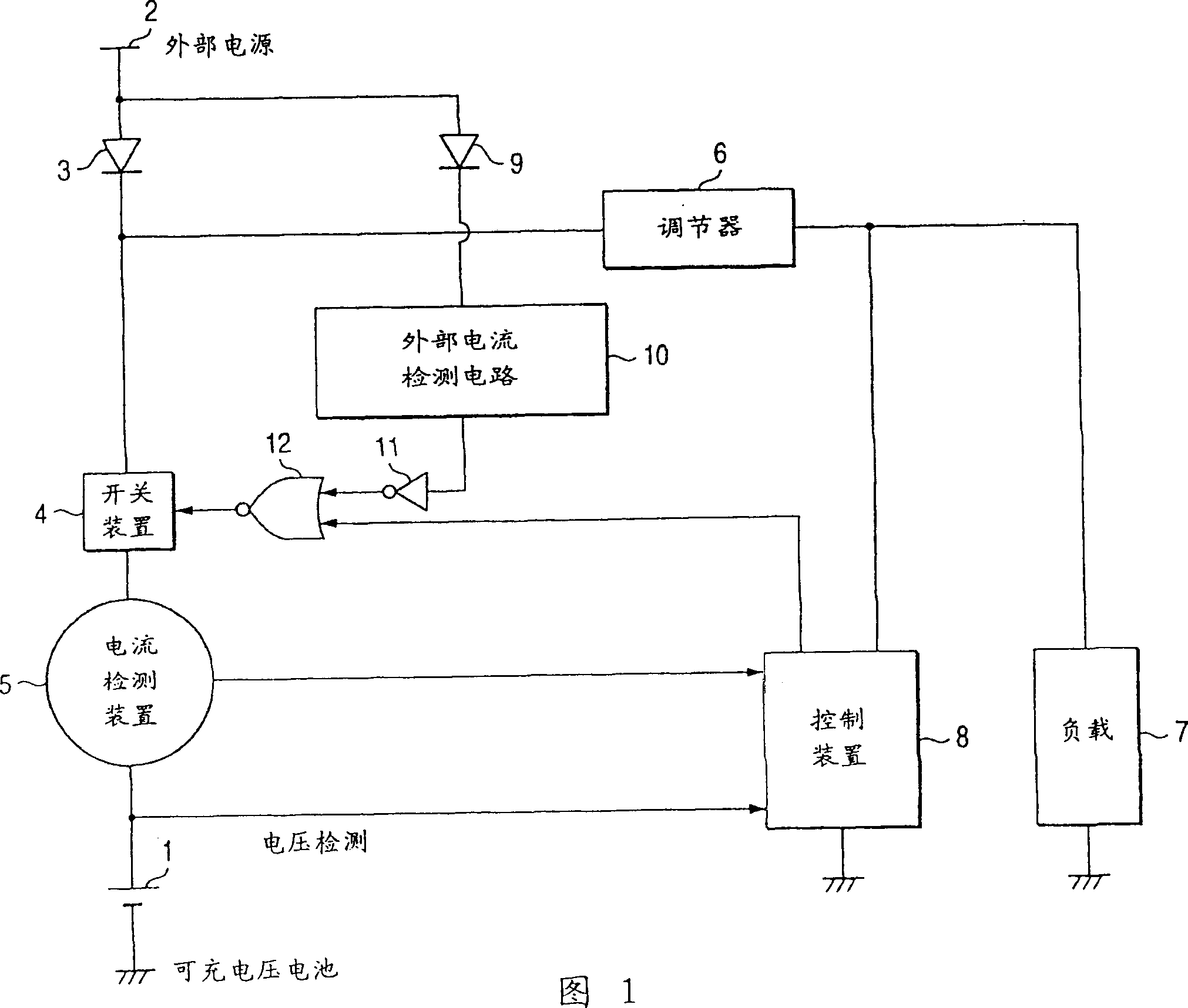
[0033] A first embodiment of the present invention is an electronic appliance having a charging function, in which a switching device is provided, and a power supply voltage is applied to a load from a node between an external power source and the switching device, and when a charging operation is performed, the switching device When the charging operation is completed, the switching device is turned off; when the external power source is disconnected from the electronic appliance, the switching device is turned on.

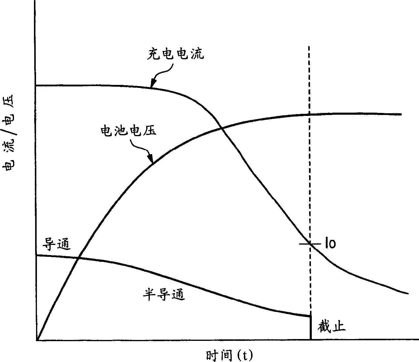
[0034] FIG. 1 is a functional block diagram showing an electronic appliance having a charging function according to a first embodiment of the present invention. figure 2 is a schematic diagram for explaining the operation of the electronic appliance with a charging function.

[0035] In FIG. 1 , an input terminal 2 of an external power supply is connected to a rechargeable battery 1 through a reverse current blocking diode 3 , a switching device 4 and a current ...

no. 2 approach

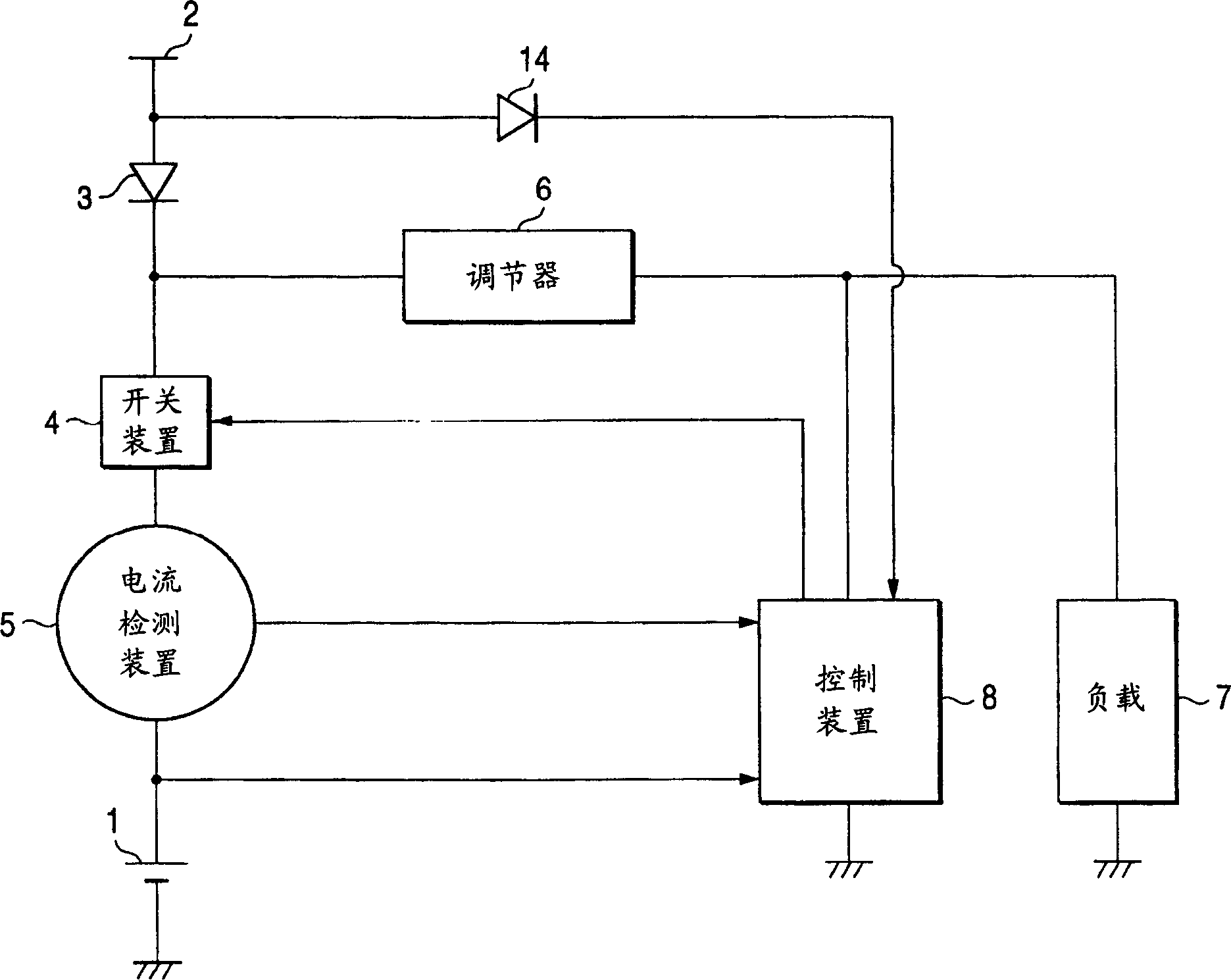
[0049] In the first embodiment, when the external power is not applied, the external power detection circuit 10 is separately provided for detecting the external current. In the second embodiment, means for detecting the application state of the external power supply voltage is provided in the control device 8 .

[0050] image 3 is a functional block diagram of an electronic appliance having a charging function according to a second embodiment of the present invention. It should be understood that in image 3 The same reference numerals are used in FIG. 1 to denote the same circuit elements. The difference of this electronic appliance is that the diode 13 is connected to the external power supply 2, and the output side of the diode 13 is connected to the control device 8. At this time, the connection and disconnection of the external power supply 2 are directly detected by the control device 8. Even when the electronic appliance is configured in this way, it can be easily ...

no. 3 approach

[0057] Figure 4 is a schematic principle diagram for explaining a third embodiment of an electronic appliance having a charging function according to the present invention. Figure 5 is a schematic diagram for explaining the operation of each unit of the electronic appliance according to the third embodiment.

[0058] exist Figure 4 Among them, the input terminal 2 of the external power supply is connected to the rechargeable battery 1 through the reverse current blocking diode 3, the switch device 4 and the current detection device 5. At this time, the regulator 6 is connected to a circuit point on the switching device 4 on the external power supply side, that is, a connection point between the diode 3 and the switching device 4 . The voltage regulated by the regulator is applied as a power supply voltage to the first load 7 and the control device 8 constituting the electronic appliance.

[0059] At this time, the second load 13 is directly connected to the rechargeable ...


PUM


Abstract

An electronic apparatus having charging function in which a secondary cell does not discharge even if the electronic apparatus operates during charging. When an external power input terminal (2) of the electronic apparatus is connected to an external power source, charging current flows to the secondary cell via a diode (3), switching means (4), and current detection means (5) and the secondary cell is charged. Control means (8) monitors the charging current and turns OFF the switch means (4) when the secondary cell (1) is fully charged and the charging current has become below a predetermined value. When the switch means turns OFF, the external power source is electrically disconnected from the secondary cell (1) and discharging of the secondary cell is prevented. When the external power source remains connected, the external power is supplied to a load (7) and the control means (8) via a regulator (6). In this case also, the secondary cell does not discharge and the fully charged state can be maintained.

Description

technical field [0001] The present invention relates to an electronic appliance having a charging function and equipped with a rechargeable battery, such as a portable phone and an information terminal device. Background technique [0002] In general, electronic appliances such as portable phones and information terminal devices that use rechargeable batteries as power sources have a function of charging these rechargeable batteries. [0003] Figure 7 It is a block diagram of a general-purpose mobile phone with a conventional charging function. exist Figure 7 In the case where the rechargeable battery 1 is charged, an external power source obtained from a power adapter (not shown), a charging device (not shown), and a car connector (not shown) well known in the art, and The input terminal 2 of the external power supply is connected. [0004] When the external power source is connected to the input terminal 2, the charging current will enter the rechargeable battery 1 thr...

Claims


Application Information

Patent Timeline
IPC IPC(8): H02J7/00
CPCH02J7/0077Y10T307/826H02J7/0032H02J7/0068H02J7/00712
Inventor 礒道康弘奥启之
Owner PANASONIC CORP
Why Eureka
Try Eureka