Means for ladling food from cooker automatically, and said cooker
A technology of cooking utensils and driving devices, which is applied to cooking utensils, household utensils, kitchen utensils, etc., to achieve high-quality results
- Summary
- Abstract
- Description
- Claims
- Application Information
AI Technical Summary
Problems solved by technology
Method used
Image

Examples
Embodiment Construction
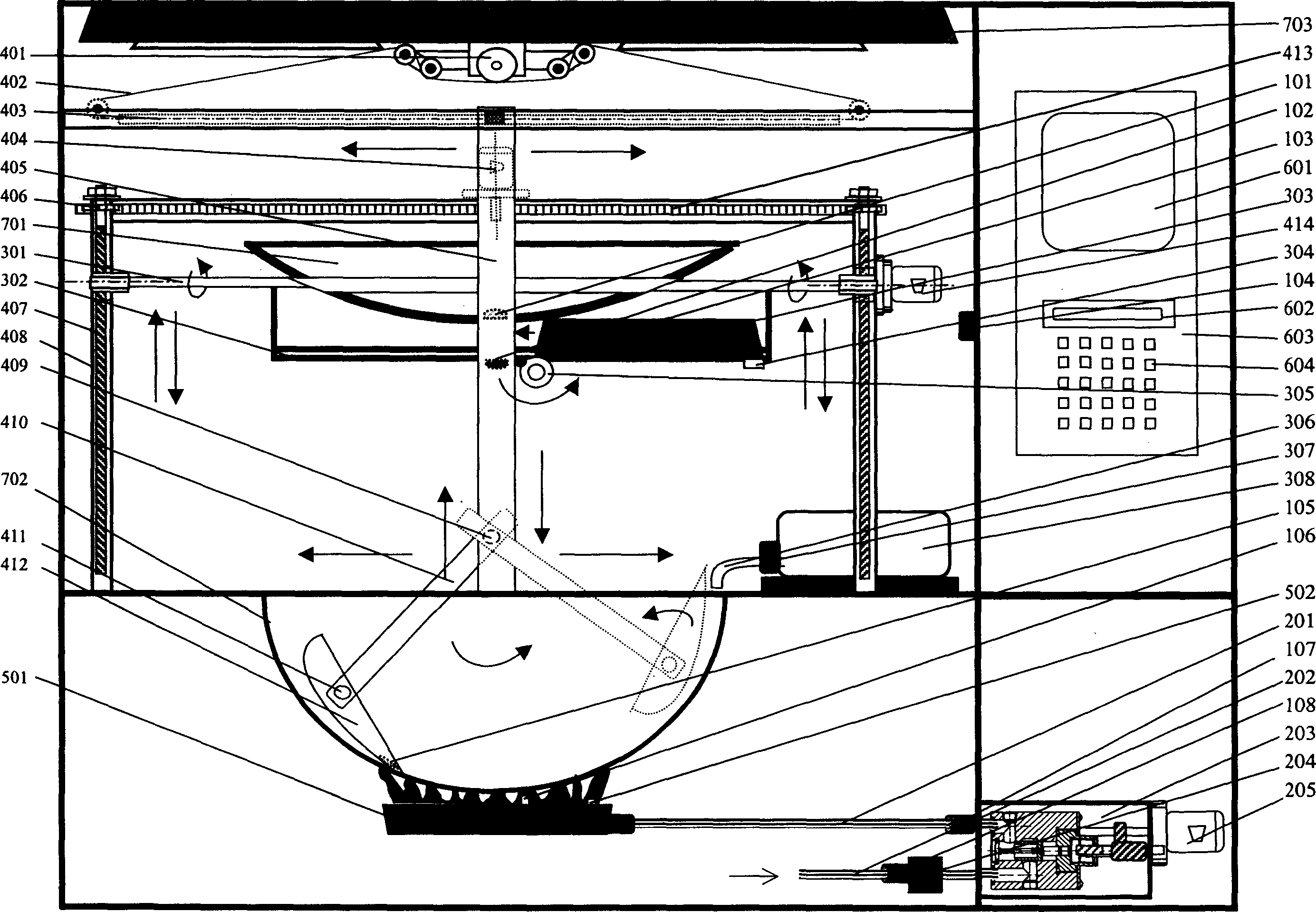
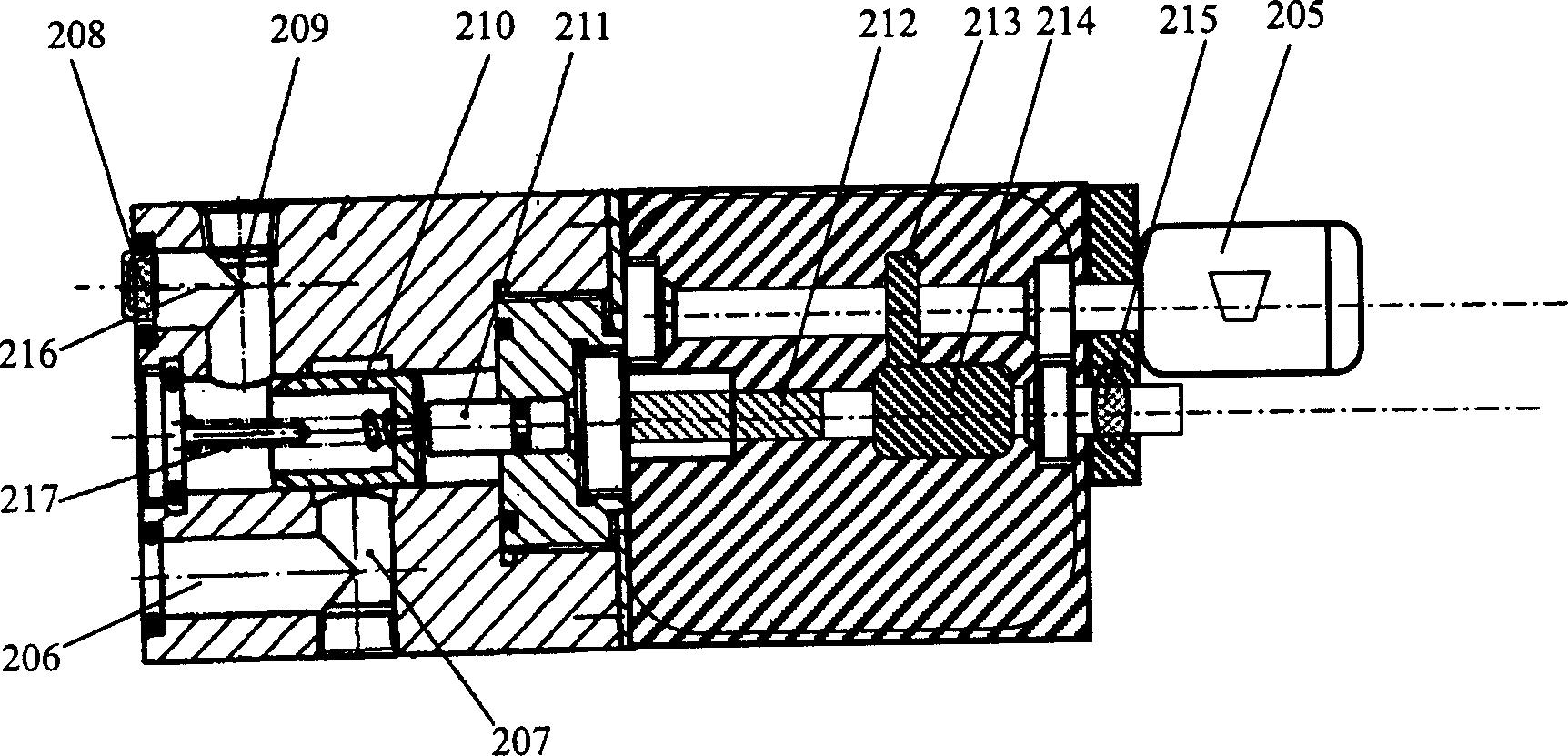
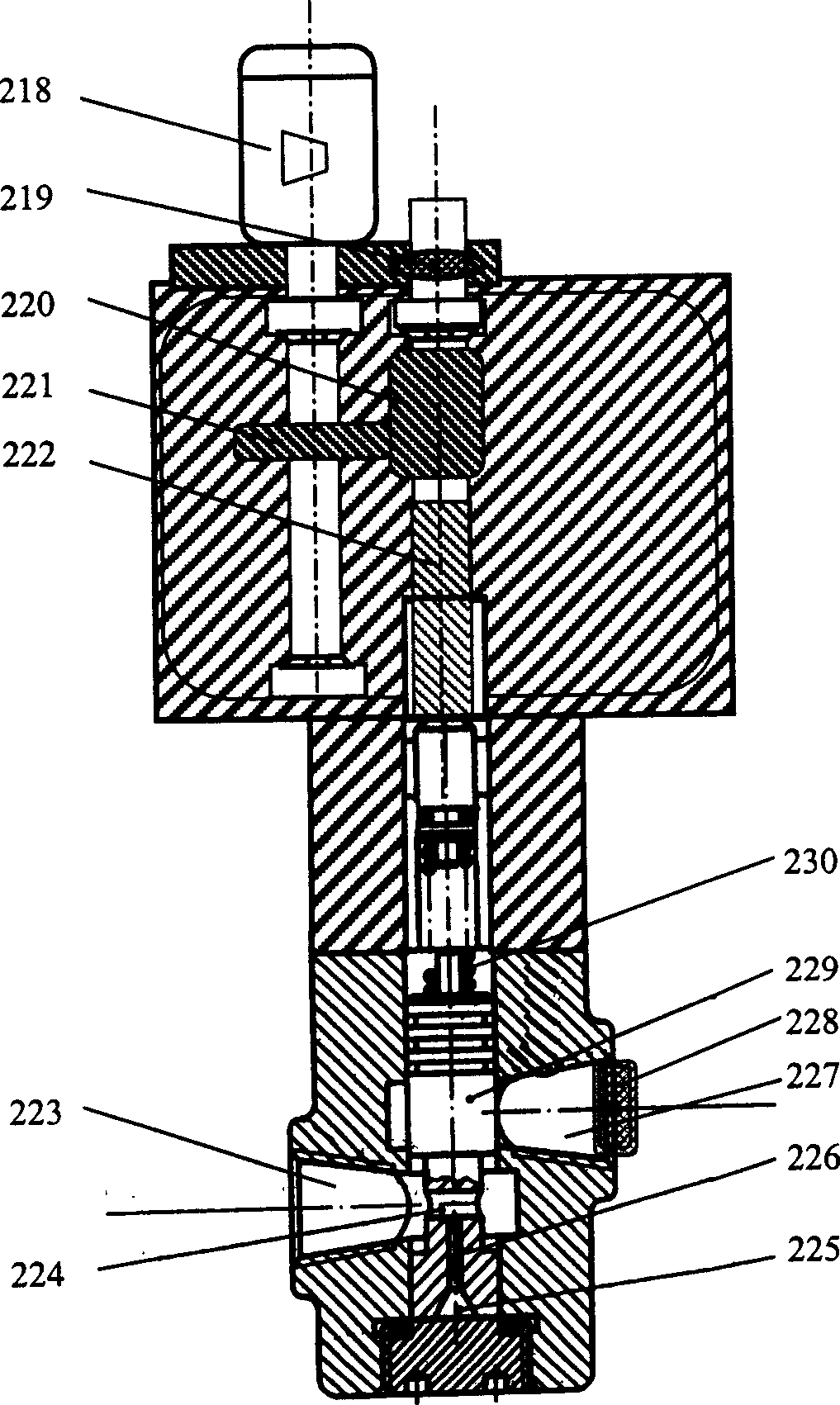
[0053] One of the embodiments of the present invention's turning and filling device is as Figure 12 , Figure 13 Shown is a flip and serve device. Stirring / full out body 420 is a shovel-like object, and one side is a shovel mouth, and the other three sides are inclined planes or curved surfaces, and its bottom is a curved surface shape, similar to the shape of the bottom of a pot, and is fixed on the rotating shafts 421 and 434. The motor 436 drives the rotating shafts 421 , 434 to rotate together with the shovel 420 through a gear 437 , a chain 438 and a gear 435 . The motor 432 drives the rotating shafts 431, 418 to rotate, and drives the connecting bodies 419, 433 and the shovel 420 to rotate together. The motor 424 drives the rotating shafts 431 , 418 through the gears 425 , 422 , 427 , chain 423 and lead screws 416 , 429 to move up and down along the supports 417 , 430 together with the connectors 419 , 433 and the shovel 420 . The support beam 426 moves along the chu...
PUM
 Abstract
Description
Claims
Application Information
PatSnap Eureka turns technology decisions into work you can execute. Powered by our Innovation Knowledge Graph, it runs expert workflows across engineering, life sciences, materials and intellectual property. Get your review-ready output in minutes.


