Steady flow valve

A steady flow valve and throttling valve technology, applied in the field of hydraulic components, can solve problems such as large system power loss, hydraulic system pollution, and installation difficulties, and achieve stable single-channel output flow, low system power loss, and a wide range of adaptability to the environment Effect

Inactive Publication Date: 2003-12-24
ZHEJIANG UNIV
View PDF0 Cites 8 Cited by
  • Summary
  • Abstract
  • Description
  • Claims
  • Application Information

AI Technical Summary

Problems solved by technology

However, some of the existing steering systems do not have good unloading components, and the power loss of the system is relatively large; some of them are not compact in structure and difficult to install; some of the control valves have more slender damping holes, their structure is complex, and it is difficult to process , when the operating environment is harsh and the hydraulic system is seriously polluted, it is easy to cause blockage of the oil circuit, and the safety and reliability of the system are poor.

Method used


Image

  • Steady flow valve
  • Steady flow valve

Examples


Embodiment Construction

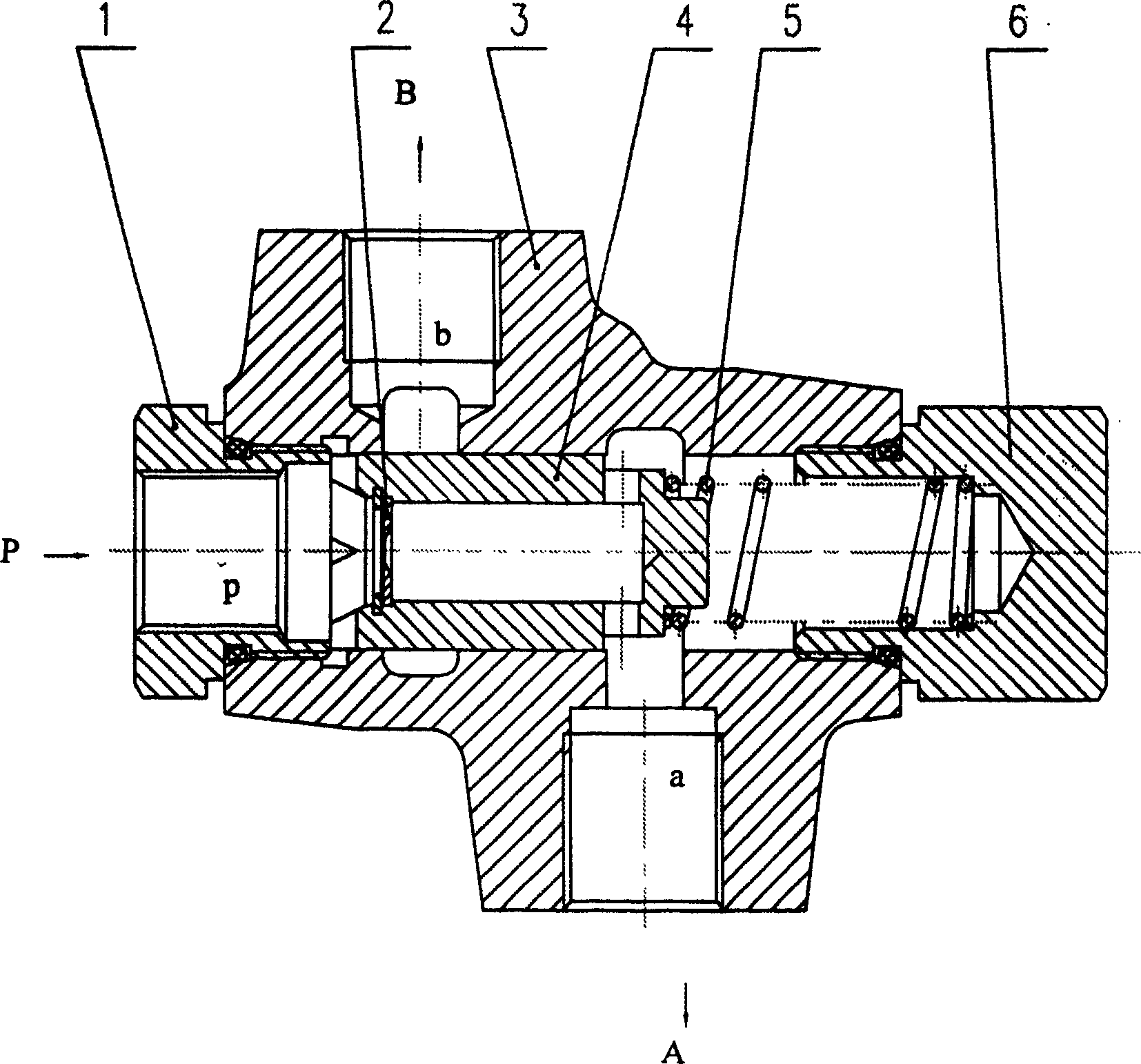
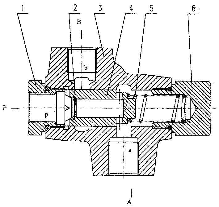
[0010] The details of the present invention are given below by describing the embodiments in conjunction with the accompanying drawings.

[0011] As shown in the drawings, the present invention includes: a joint 1 , a throttle valve 2 , a valve body 3 , a pressure compensating valve core 4 , a spring 5 , and a spring seat 6 . A joint 1 is installed on the left end of the valve body 3, and a pressure compensating valve core 4 is installed in the axial hole of the valve body 3, the small end of the pressure compensating valve core 4 is covered with a spring 5, and the right end of the valve body 3 is equipped with a spring seat 6 There is an axial hole in the center of the pressure compensation spool 4, and radial through holes communicating with the axial hole are respectively opened at the left and right ends of the axial hole, and the throttle valve 2 is installed in the axial hole of the pressure compensation spool 4 On the left end face of the valve body 3, there are valve ...


PUM


Abstract

A flow stabilizing valve is composed of valve body with left jointer, valve core in the axial hole of valve body and having a central through hole and two radial through holes at its both ends, spring sleeving on small end of valve core, spring holder at right end of valve body, and a throttle valve installed at left end of said central through hole on valve core. On the valve body, there is an outlet A with stabilized flow and another outlet B for excessive flow. When load is changed, the orifice area of said radial through holes on valve core can be automatically changed for pressure compensation, stabilizing the output flow.

Description

technical field [0001] The invention relates to a hydraulic component characterized by hydraulic control technology, in particular to a steady flow valve for flow control of a hydraulic system. Background technique [0002] In the field of background technology, a flexible and portable hydraulic power assist power system has been widely used in the steering control of construction machinery. The working pressure of the system during the steering process depends on the road conditions. On a flat road, the working pressure of the system is relatively low due to the relatively small driving resistance. On the contrary, the work pressure is higher. Therefore, a good flow control system is required to stabilize the steering. However, some of the existing steering systems have no good unloading components, and the power loss of the system is relatively large; some are not compact in structure, and it is difficult to install; some control valves have mo...

Claims


Application Information

Patent Timeline
Patent Type & Authority Applications(China)
IPC IPC(8): F16K17/04G05D16/10
Inventor 魏建华
Owner ZHEJIANG UNIV
Why Eureka
Try Eureka