

Pointing device for position
A technology of indicating devices and output devices, which is applied to measuring devices, indicating/recording actions, devices using fluids, etc., can solve problems such as pointers cannot move, and achieve the effect of improving accuracy and sensitivity
- Summary
- Abstract
- Description
- Claims
- Application Information
AI Technical Summary
Problems solved by technology
Method used
Image

Examples
Embodiment 1
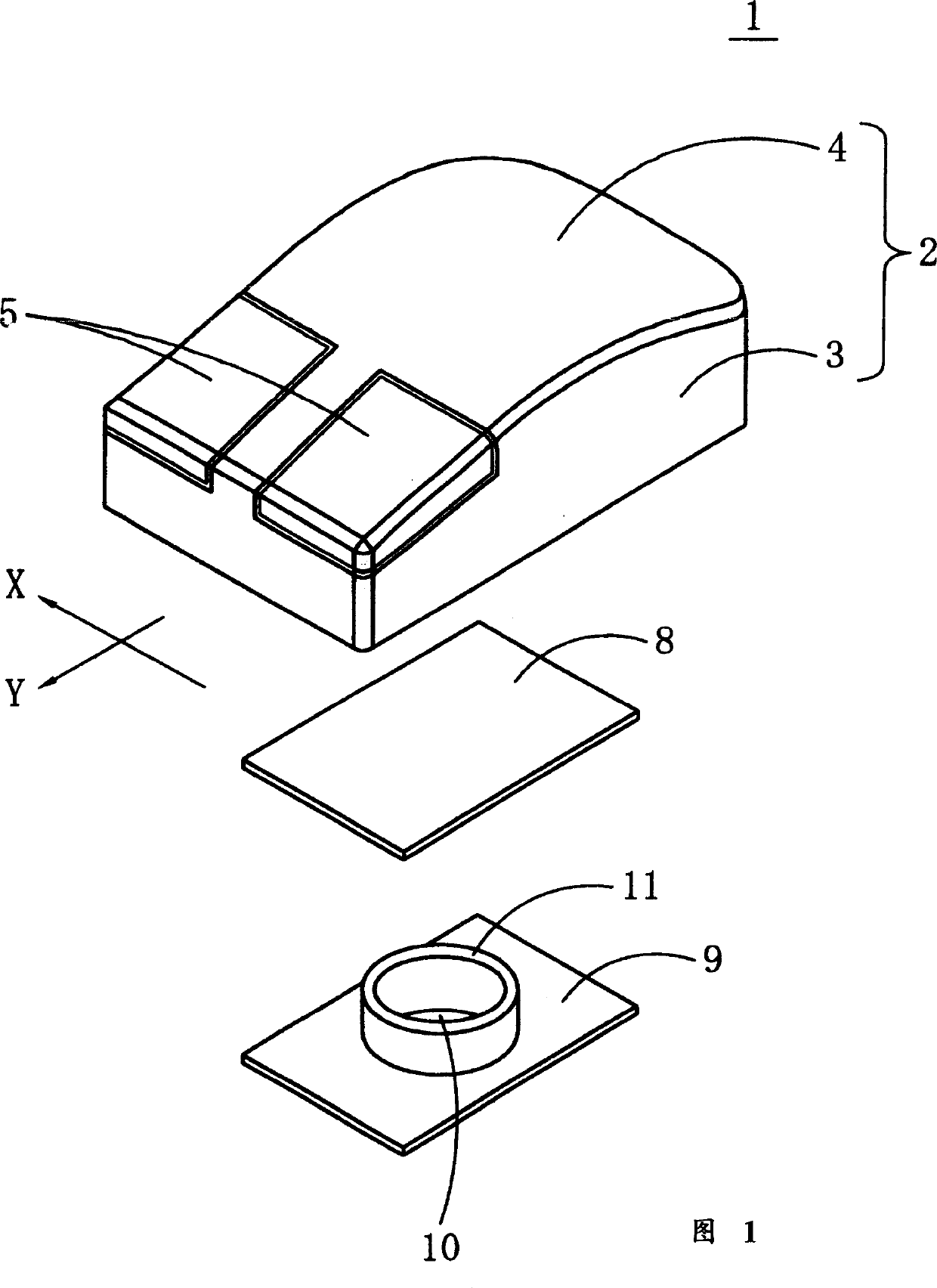
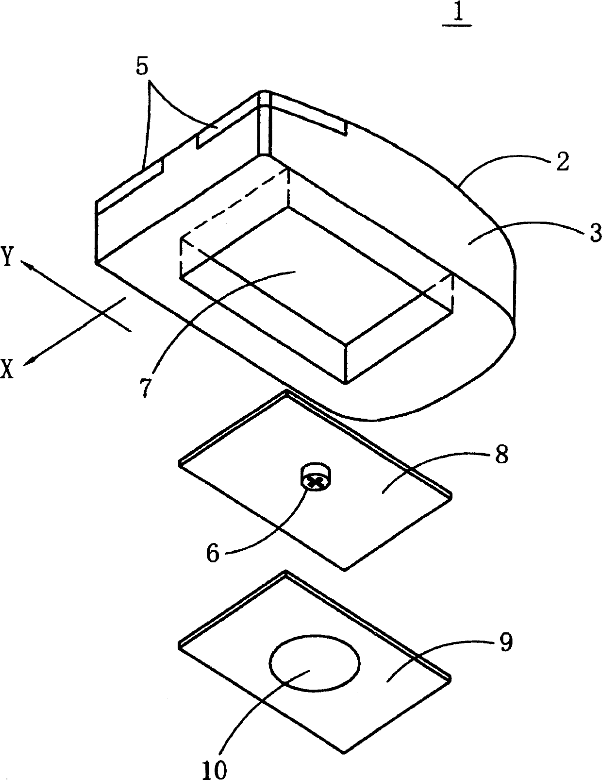
[0093] 1 and 2 are an exploded perspective view from above and an exploded perspective view from below showing the structure of a mouse 1 (mouse-type position pointing device) according to an embodiment of the present invention. The mouse housing 2 is composed of a housing body 3 with an upper opening and a housing cover 4 that covers the upper opening of the housing body 3 and is installed. Two click buttons 5 are provided on the front portion of the case cover 4 , and a signal processing circuit (not shown) for generating a signal by operating each click button 5 is accommodated in the mouse case 2 . The front portion of the mouse housing 2 in the illustrated example has two click buttons 5, but it may also have more than three click buttons or have a rotating wheel.
[0094] The bottom surface of the mouse case 2 is provided with a recess 7 for accommodating the flow sensor 6 . The flow sensor 6 is housed in the recess 7 of the mouse case 2 while being mounted on the lower...
Embodiment 2
[0112] Fig. 17 is an exploded perspective view showing the structure of a mouse according to another embodiment of the present invention viewed obliquely from above, and Fig. 18 is an exploded perspective view viewed obliquely from below. The mouse 51 is as follows. When the mouse 51 is picked up from the operation surface 30, the opening of the sensor storage chamber 26 is sealed, and the flow sensor 6 becomes a non-detection state. When the mouse 1 is placed on the operation surface 30, the sensor storage chamber 26 is closed. The opening is opened, and the flow sensor 6 is in a detection state.
[0113] Therefore, in this embodiment, the flow sensor 6 is covered by the sensor housing 52 composed of the fixing portion 53 and the slider 54 shown in FIGS. 19 and 20 . The fixing part 53 is composed of a cylindrical body 55, a cover 56 under the body 55, and a flange 57 around the cover 56. A vent hole 58 is opened on the body 55, and a hole 59 for a slider is opened on the flan...
Embodiment 3
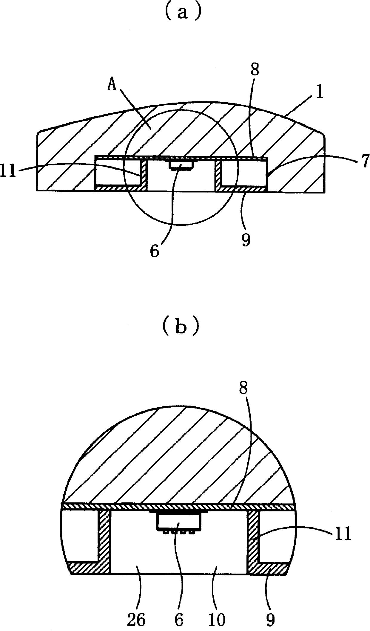
[0119]22(a), (b) are cross-sectional views showing the sensor case 52 of the mouse and its surrounding structures in still other embodiments of the present invention. This mouse has the same structure as the mouse 51 shown in FIGS. 17 to 21 , but the difference is that the cover 56 is provided on the slider 54 instead of the fixed portion 53 .
[0120] This embodiment is also when the mouse is picked up from the operation surface 30, as shown in Figure 22 (a), the air vent 58 of the slide block 54 descends, and the air vent 58 of the fixed part 53 is blocked with a slider 61, and the air vent 62 of the slide block 54 is also blocked with a slide block 54. The fixing portion 53 (flange 57 ) is closed, and the sensor housing chamber 26 in the sensor case 52 is substantially airtight. When the mouse is placed on the operating surface 30, as shown in Figure 22 (b), the slide block 54 is pushed up, the vent hole 58 of the fixed part 53 is consistent with the vent hole 62 of the sli...
PUM
 Abstract
Description
Claims
Application Information